Project Lead
Contents
- Introduction
- Summary
- Requirements
- Assumptions
- Applications
- MATLAB
- FreeFlyer
- Other Resources
- Launch Vehicle Trade Study
- Technical Calculations
- Observer Mission
- Primary Impact Mission
- Conclusions
1.0 Introduction
Summary
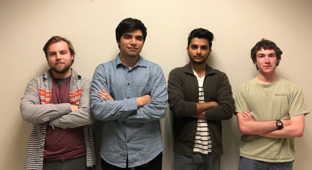
During the 2018 winter quarter at Cal Poly Pomona, I took an Orbital Mechanics course, ARO309, which covered Lambert transfers, Hohmann transfers with plane changes, and other space flight dynamics. Overall, I found ARO309 to be one of my favorite classes on campus so far because of the topics covered. Dr. Lantoine, a JPL mission designer, instructed the class and was very helpful in explaining the process of searching for trajectories. Working with me were Jehosafat Cabrera-Guzman, Daniel Schwall, Nick Shewchuk, and Ibram Ghobrial (not pictured).The project was successful and my team and I had the highest grade in the class for our presentation and trajectory values.
Requirements
The goal of the project was to simulate an asteroid impact mission which would successfully deflect PDC17A, a fictional Earthbound asteroid created by the NASA’s CNEOS program. With the use of a kinetic impactor(s), the asteroid’s new flight path change would need to be sufficient so that it would not return to Earth in the next 20 years after the impactor mission.
Assumptions
- Discovery Date: March 6 2017
- Potential Impact Date: July 21, 2027
- Eccentric Orbit
- Orbital Period 1225 days (3.35 years)
- Inclination: 6.3 deg. to earth’s orbital plane.
- Mass: 2.651e9 kg
- Porous Rock (⍴ = 1.5 g/cm^3)
- Lambert Assumptions:
- Two Body Assumption
- Earth Parking Orbit – 200 km
- Delta IV will have sufficient fuel to provide the delta V until leaving Earth’s SOI (setting the impactor on the hyperbolic transfer)
- PDC17A does not have a considerable gravitational field
- Impulsive burns and impacts
2.0 Applications and Models
MATLAB
Mathworks MATLAB was the primary program used in order to compute deflections and study the trajectory. I took this project as an opportunity to learn about the program and how to write MATLAB code. The primary deflection computation was done with a series of .m files that I created that would import ephemeris data files, call textbook .m files for Lambert transfer calculations, and output final computations both graphically and analytically. My team used Orbit Hangar’s Trajectory Optimization Tool V2.1 that used MATLAB for their scout mission deflection and orbital parameter calculations.
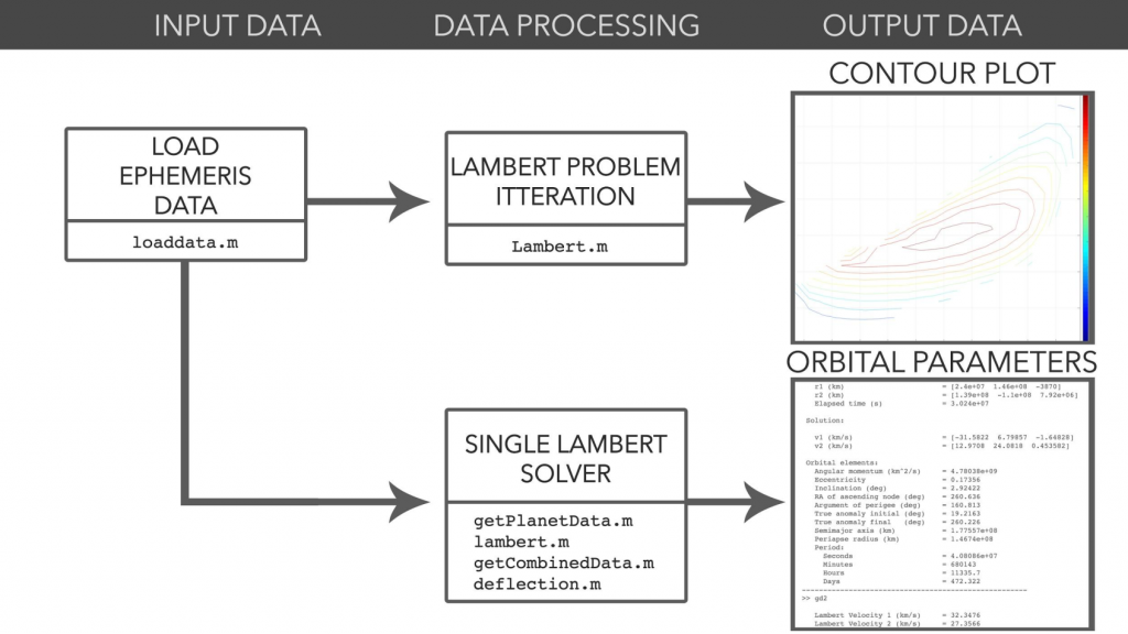
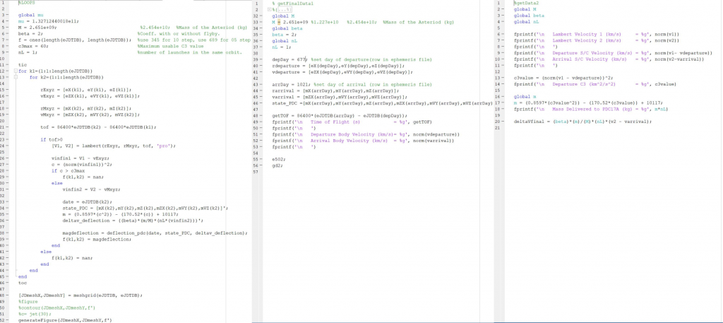
The ephemeris files were prepared beforehand from the NASA Horizons website. The appropriate dates and time steps were factored in here and so I had a 10 day step ephemeris file set and a 1 day file set. This made searching for the trajectory initially less computer resource intensive. Once an time window was established, I used the 1 day step to narrow in and acquire specific orbital parameters of the trajectory to fine tune our search. The graphical depiction used the 10 step file, hence the spaces in the contour plots, and the elements file used the 1 day step file. After the ephemeris files were loaded and parsed, The solving stage processed the data by calling lambert.m, a textbook .m file for MATLAB, and began saving deflection or velocity points given the input conditions I requested.
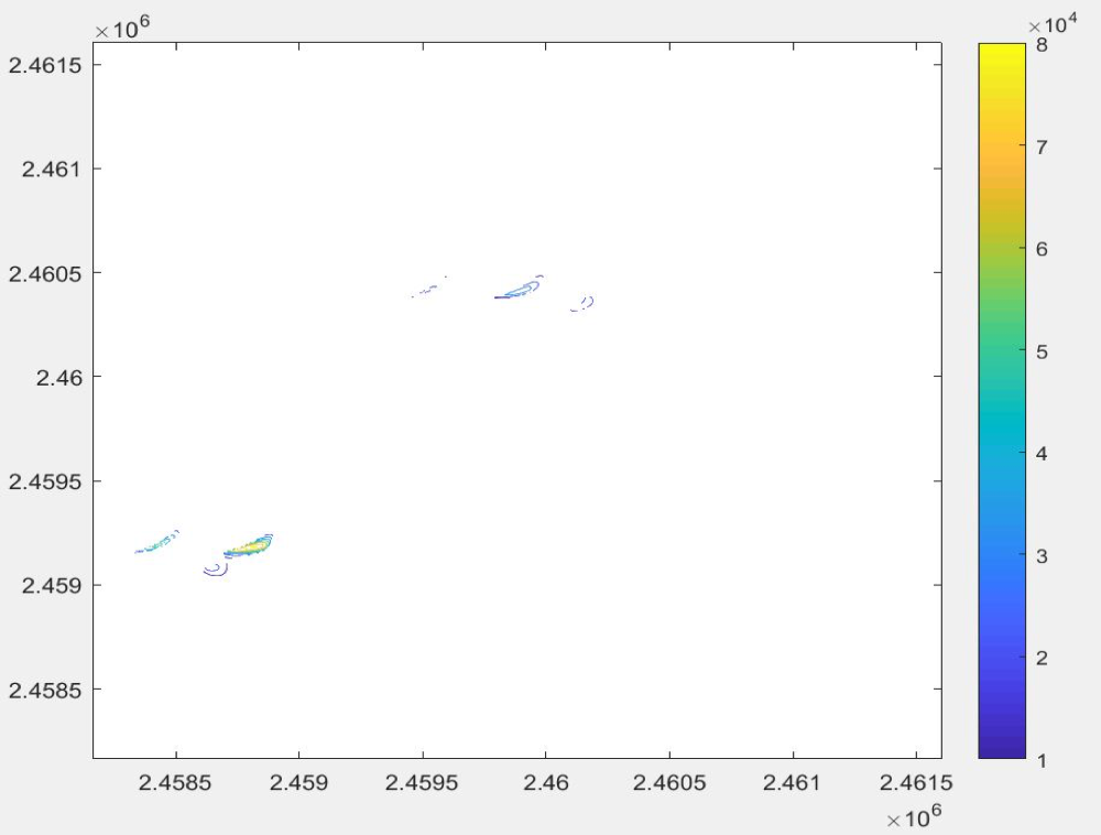
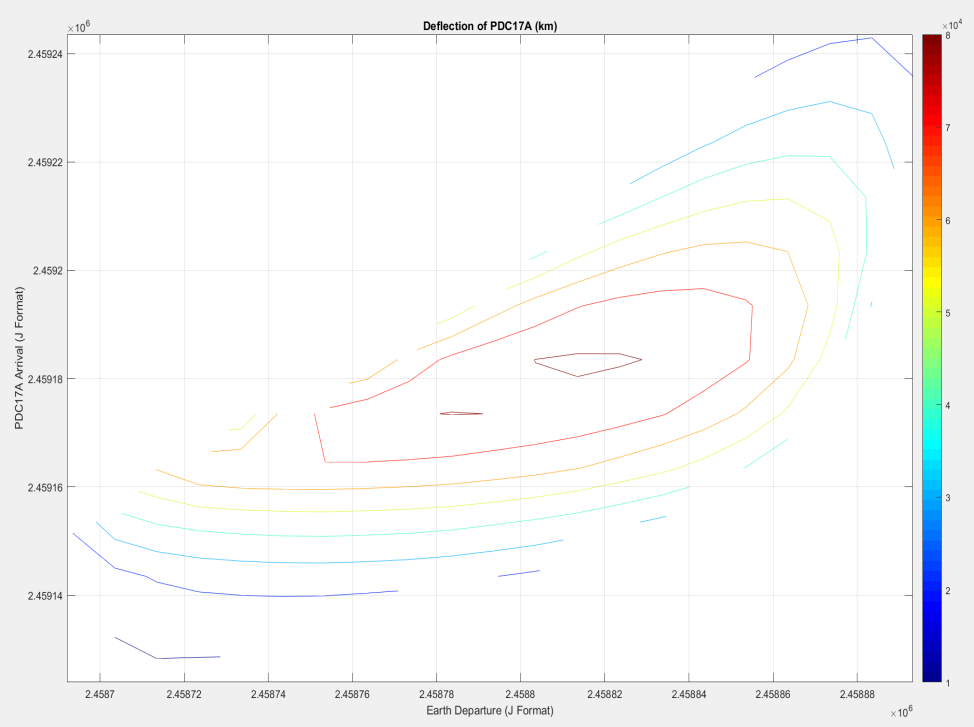
The X-Axis and Y-Axis are Julian days for Earth departure and PDC17A arrival respectively. The contours represent the immediate deflection of the asteroids. Later, orbital elements were pulled based on specified Julian days as discussed later on. Overall, this project taught me the basics of MATLAB and was a bonus for our project’s overall score.
FreeFlyer

A.I. Solutions FreeFlyer 7.3 was an incredibly useful resource to visualize deflections and understand more about the orbits of the Earth, PDC, and other celestial bodies. We used it for orbit validation, visualization, future outlook calculations, and the graphical aspects of the project. By running the simulation another twenty years in the future, FreeFlyer would give us an analysis of the position of PDC17A relative to Earth with statistical data as well.
Other Resources

A couple NASA websites proved to be very handy for our project. Starting with Horizons. It tabulated, as many requirements or information we needed for our search. Another website that was critical was Launch Vehicle Services. This site gave us the information we needed for injection energy and deltaV of various launch platforms. Finally, the NEOS deflection website and the CNEOS Planetary Defense sites were used for more information about PDC17A and possible starting points for our project.
3.0 Launch Vehicle Trade Study
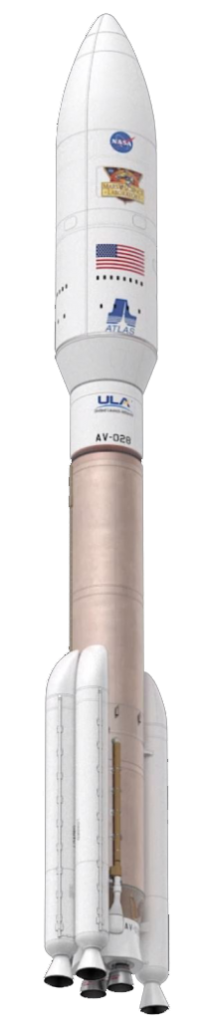
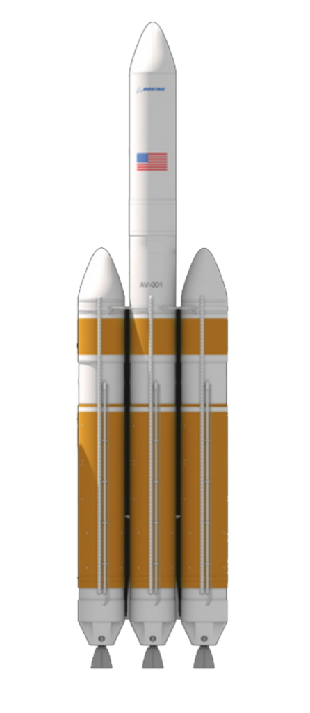
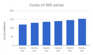
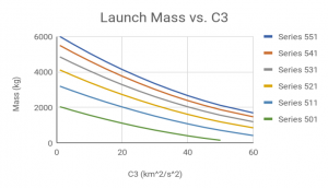
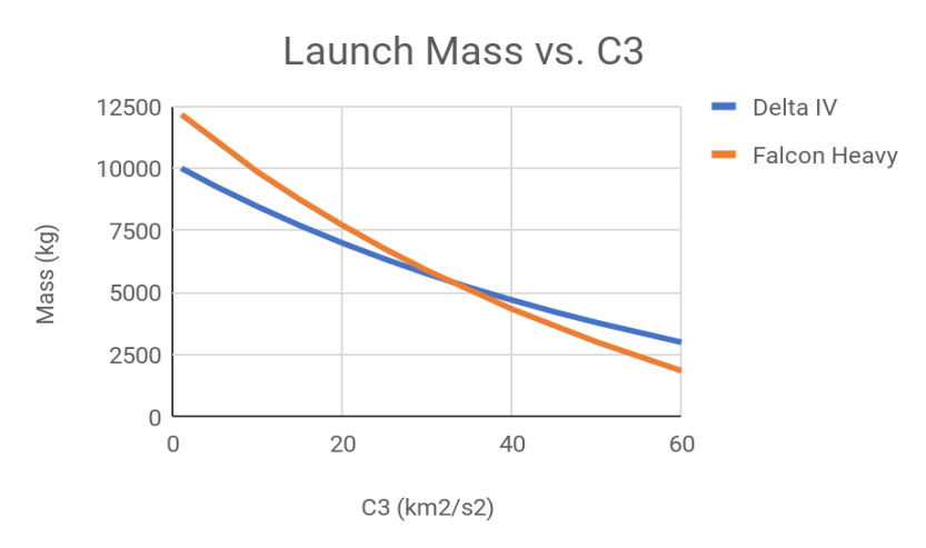
It was determined through a trade study that the ULA Atlas V 500 was the most cost efficient and high energy option that would satisfy the high C3 requirement of the scout mission. At 45.68 km^2/s^2, the scout mission was designed to be fast and early to gather enough data about PDC17A before launching the impactor. The only rocket that would deliver the probe into this kind of orbit was the Atlas V series. For the main mission, there was a choice between the new SpaceX Falcon Heavy or the ULA Delta IV Heavy. We opted for the Delta IV Heavy because of its proven reliability, only one partial failure in 35 missions. It was significantly more expensive to launch but it was still a reliable platform. We compared the mass capability to injection C3 with numbers provided from the NASA Launch Vehicle Services website.
4.0 Technical Calculations
Observer Mission
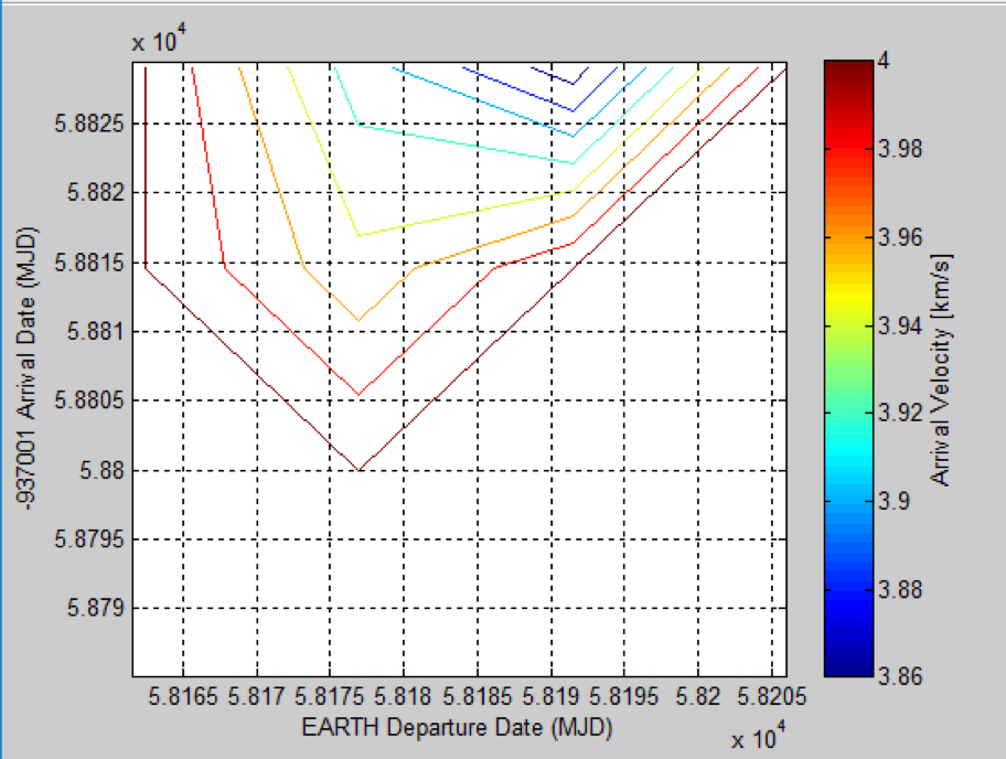
The observer mission was created in order to study the asteroid and return critical data back to Earth to further design the kinetic impactor trajectory. We selected, based on the generated contour plot, that an immediate, but less efficient departure was necessary to reach PDC17A. The higher C3 meant that our launch vehicle would have to be more robust but it would be beneficial to have extra time to decide the kinetic impactor’s properties.
OBSERVATION MISSION
- Departure Vehicle: ULA Atlas V 541
- Departure Day: June 16, 2018
- Departure Velocity:
- Arrival Day: December 12, 2019
- Arrival Velocity: -2.29 km/s
- TOF: 543.3 days
As seen on the right, the regions in blue were desired for the scout mission as a high approach C3 meant more propellant required to reduce the energy. This is contrary to that of the kinetic impactor. Below is a visualization in FreeFlyer of the trajectory of the observer mission.
Primary Impact Mission
For the primary impactor, a porkchop plot was created using an iterative solution from the Lambert transfer. Ephemeris files for Earth and PDC17A were pulled from JPL’s Horizons Database and were imported as workspace files in MATLAB. These were sorted into arrays containing their radii from the sun and velocity vector components. The Lambert transfer code, which was used from Orbital Mechanics for Engineering Students (Howard D. Curtis), was called as a function to solve each combination of given radius from the sun and heliocentric velocity components. Several “if” statements were added to reduce the calculation time and remove data that was not usable for the mission. Below is the porkchop plot created after also accounting for PDC17A’s deflection.
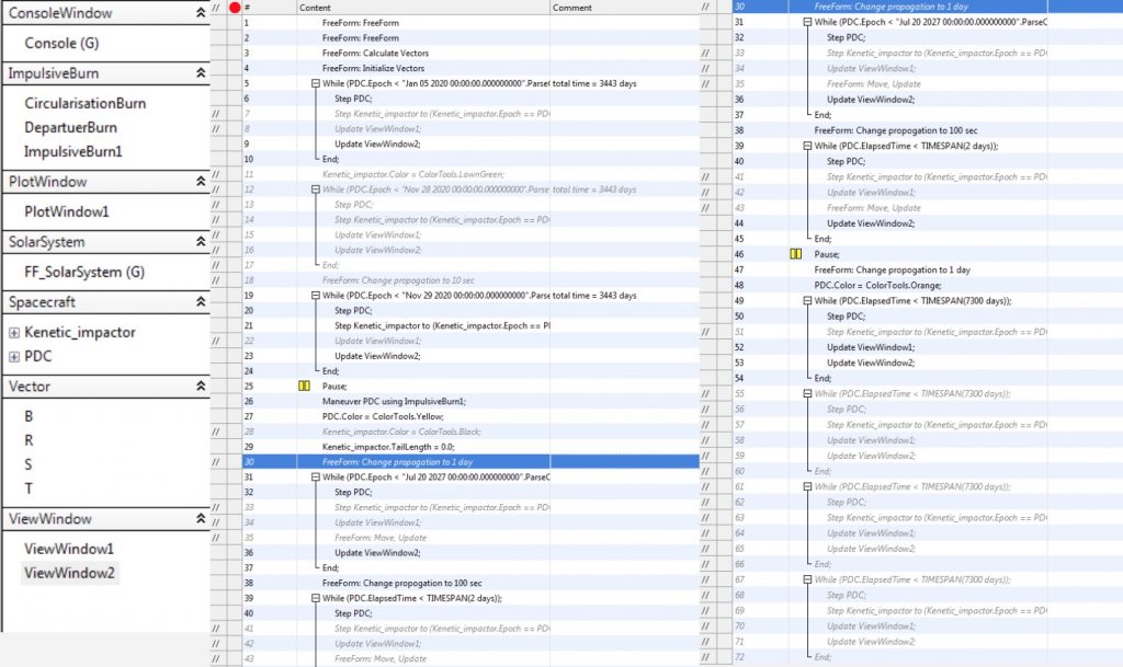
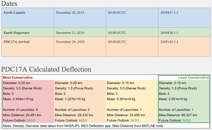
A timeline was generated which indicates the possible launch days and times, systems check, and the kinetic impactor arrival at PDC17A. Our group opted to create a chart that shows the conditions of PDC17A and its deflection due to the kinetic impactor based on a conservative approach. Due to the requirements met, we were able to opt for the least conservative choice from the professor which yielded a single impact that would satisfy the deflection and future outlook. The evaluation team found this approach to the problem insightful and commented on it being useful for future projects.
Our final mission sequence is visualized below.

5.0 Conclusion
Overall, designing the asteroid impact mission in ARO309 was a useful project that helped my team and I better understand MATLAB, FreeFlyer, Lambert transfers, and the introduction to space mission design. We successfully created a scout and impact mission that satisfied the mission statement. I would like to thank Dr. Lantoine for helping me understand MATLAB and how to use it effectively. His help and lectures on orbital mechanics were the beginning of my fascination in the subject.