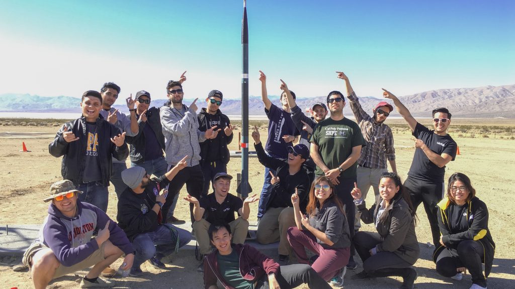
Aerodynamics Team and CAD Team Member (2017-2018)
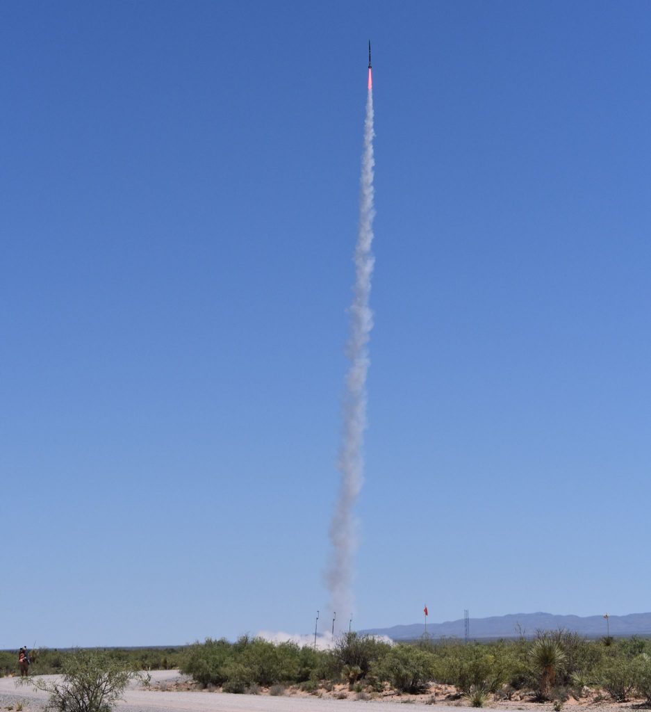
Photo Courtesy of Rick Maschek (Team Adviser).
Contents
- Summary
- Rocket Geometry and Components
- Aerodynamics
- OpenRocket Simulation
- Nose Cone
- Fin Geometry
- Divergence and Flutter
- Computational Fluid Dynamics
- Launch Vehicle Stability (LVS)
- Subscale Tests
- Building the Fullscale Rocket
- The GPS Sled
- Fin Construction
- Fin MountAssembly
- Mounting and Finishes
- Fullscale Launch
- Conclusion
1.0 Summary
Over the course of nine months, the team worked on designing, building, and launching two high powered rockets for the Spaceport America 2018 competition. In February of 2018, the first sub-scale launch took place and gave us an idea for propellant types, materials, and helped my team specifically work on improving our aerodynamic stability. We eventually designed and built the full scale competition rocket but experienced an RUD, rapid unscheduled disassembly, due to out-of-margin motor performance. While this resulted in loss of the vehicle, the experience taught us more about vehicle performance and safety margins. More on the analysis is covered in this short report.
2.0 Rocket Geometry and Components
The fullscale rocket stands roughly 15 feet tall with a diameter of 6 inches. There are compartments for the electronics bay, a SpaceX data collection board, dough and main parachutes, glider airplane payload box, and the engine section.
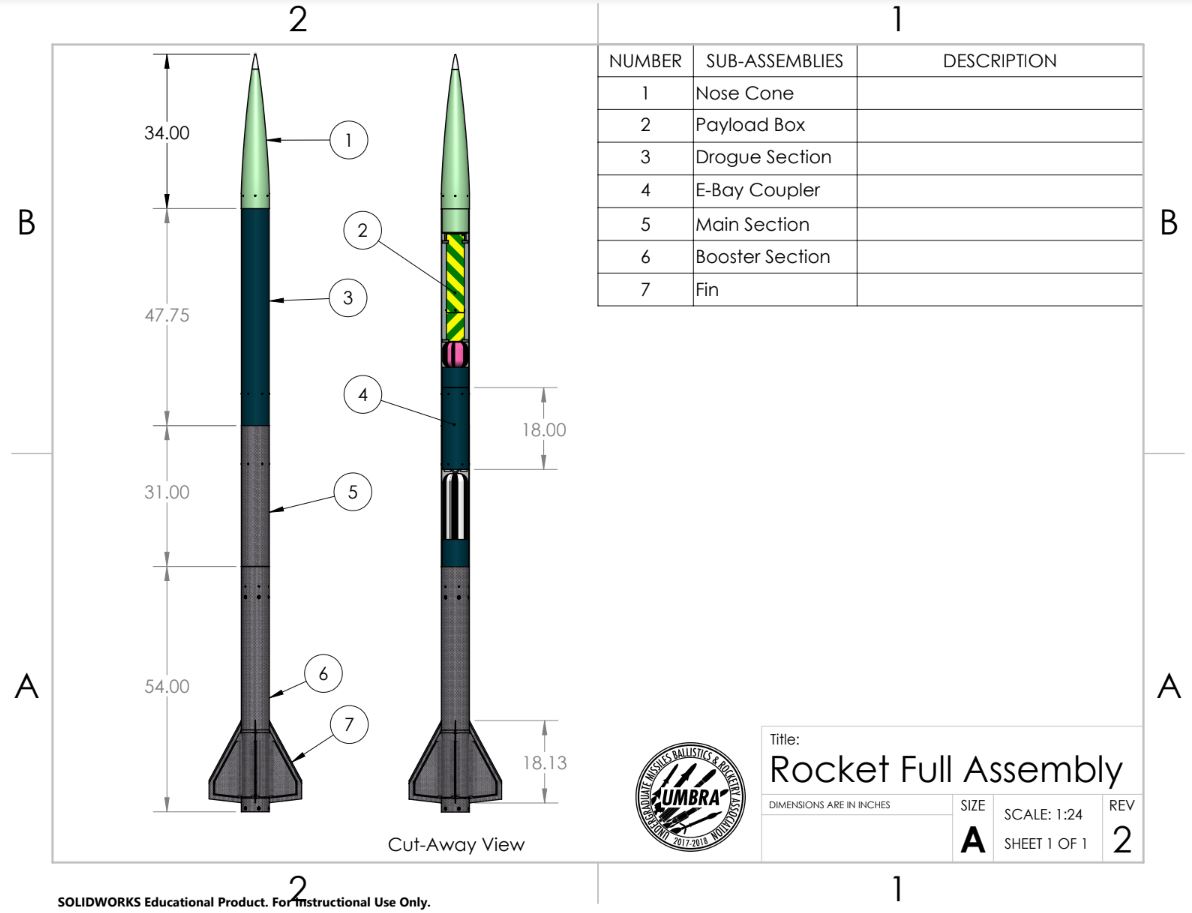
The rocket sported 3 GPS egg-finders, a flight computer, SpaceX board, a graphite epoxy nozzle, carbon fiber and blue tube sections, a fiberglass nose, and 5 parachutes in total using C02 canisters for ejection charges.
Our subscale vehicle was 7 feet tall with a diameter of 3 inches. It was constructed and launched twice to test systems and get an idea for AP grains.
3.0 Aerodynamics
In order to understand the rocket’s flight dynamics and performance, our team and I used several tools and calculations. Flight simulations were done on OpenRocket and RASAero. Fin flutter and divergence was calculated with Aerorocket FinSim. CAD modeling and CFD testing was done in Dassault Systems Solidworks and Flow Simulation.
OpenRocket Simulation
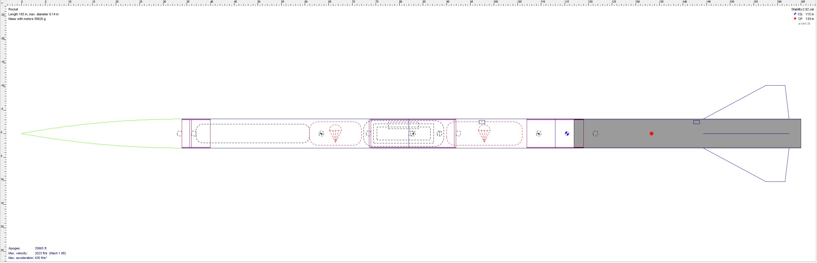

OpenRocket was the primary application to test our rocket’s flight performance. The engine thrust curve files were prepared by the propulsions group and my team and I routinely went around to various sub-teams to gather data for the weights and sizing for each part. This enabled us to generate an accurate project file which in return delivers better simulation results.
Nose Cone
The nose cone was a standard Von Karman nose spanning 33 inches long and 6 inches in diameter. We knew this design would work optimally at supersonic speeds and given the fact that the tip as aluminium, the issue of heating was also solved. Within the cone, our primary GPS unit was housed. The fiberglass construction made it optimal to store the transmitter here for a clear signal. The GPS and mount, bulk plate with a U-Bolt, and a small pilot parachute were included in this section of the fullscale rocket.
Fin Geometry
The fins would stand 7 inches tall, 16 inches in chord length, 4 inches in tip length, 13 inches sweet distance, and with a sweep angle of 30 degrees. The four fin configuration was chosen after seeing instability results in the three fin variant of the subscale. A fin can system was implemented, as seen above, which would be an inch smaller in all sides of the fin to help with flutter.
Divergence and Flutter
The fins were tall, and because of its material choice, they were quite prone to flutter. When too much energy is introduced to the system, in this case due to the airflow around the fins, flutter can excite the system which can lead to fin damage. This is similar to the Tacoma-Narrows Bridge collapse due to wind and induced osculations. Divergence occurs before flutter, and it is the point where the system becomes unstable. I used FinSim’s Classical 2-D Lift Slope CN-Alpha method to generate my figures. Our divergence and flutter testing resulted in safe operational speeds lower than mach 2.0 with divergence occurring as low as 1.6 under the most conservative relative position of the elastic axis. Flutter was inevitable after mach 2.4. More research could have been done to fine tune these numbers. We used the fin can as a way to make the fins more robust in order to handle the high mach airflow.
Computational Fluid Dynamics
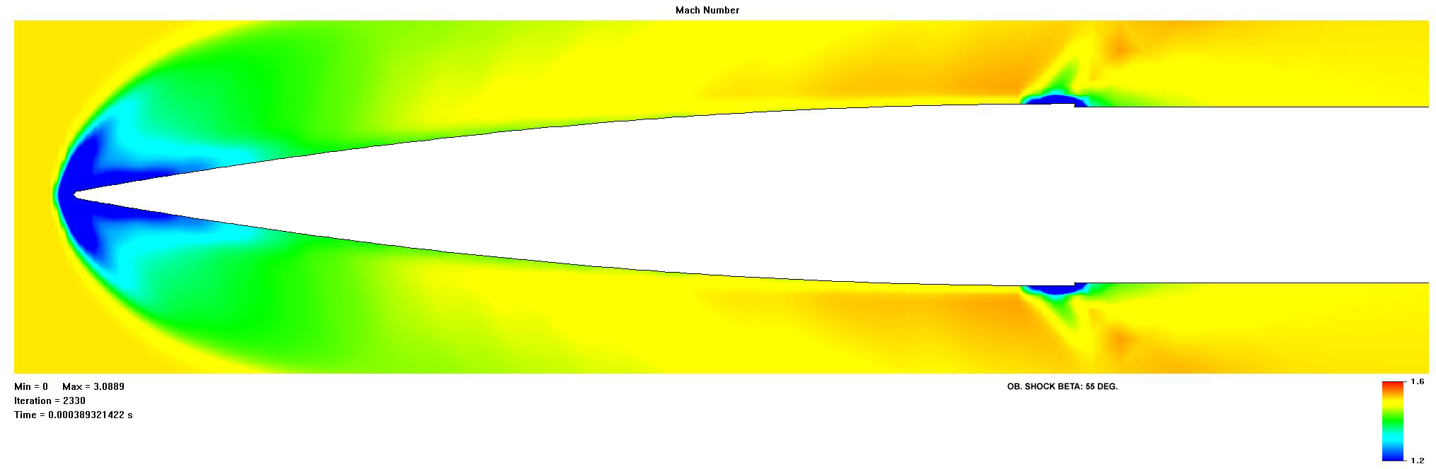
For this project, I wanted to do a basic CFD analysis on the fullscale rocket in order to get a better idea as to the shocks and airflow around the fins. I have had no experience with CFD prior to this, but I took it as a learning opportunity to understand the basics of mesh generation. ANSYS Fluent was still foreign to me at the time, but during this project I was getting the hang of Solidworks’s Flow Simulation. I generated a global and several local meshes and began the process in the solver. The results show oblique shock formation and Prandtl-Meyer expansion fan occurring after the nose cone.

At supersonic speeds, a primary concern besides shock formation is temperature. The fin leading edge temperatures need to be accounted for and so the team and I decided initially to cut small strips of aluminium to shield the vulnerable carbon fiber. This idea was later abandoned and we opted to use JB weld on the leading edges and then sanding it down to retain the beveled edge.
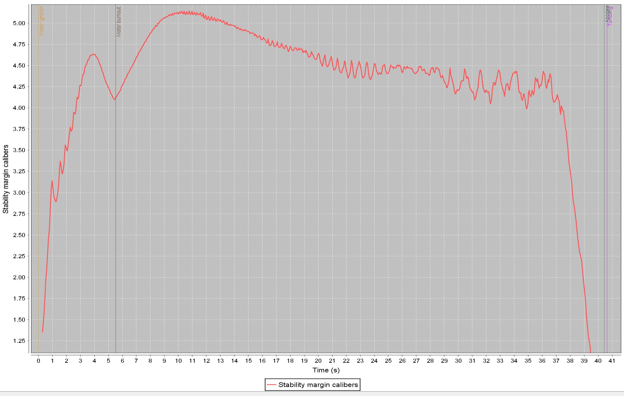
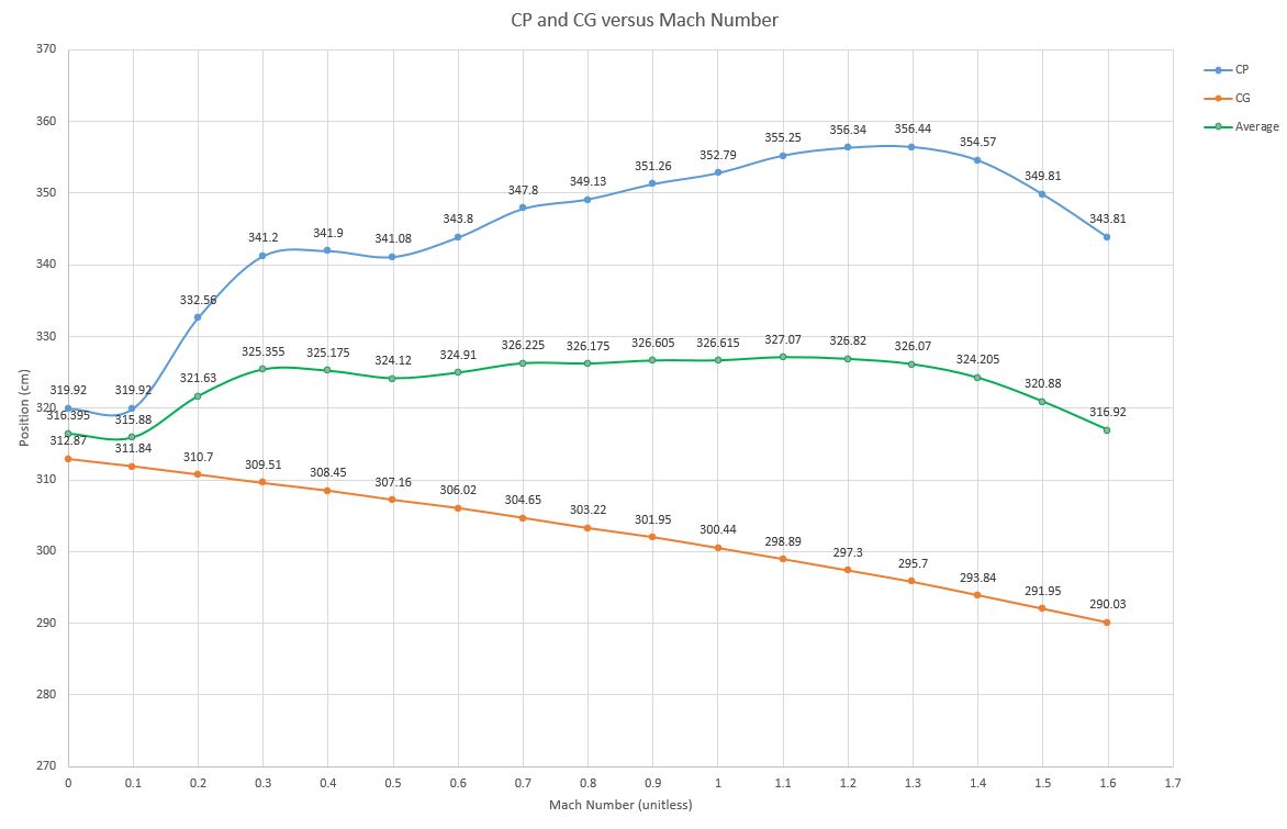
Launch Vehicle Stability (LVS)
Determining LVS is the most important job for the aerodynamics team. Aerodynamic forces during flight act at the center of pressure (CP) and can generate moments about the center of gravity (CG) thus reducing the stability. To ensure that the rocket lifts from the rail in the intended direction and continues to climb normal to the ground, an appropriate rail velocity and stability must be ensured. In flight simulation trials, the fullscale rocket’s rail exit velocity is 115 feet per second and the off the rail stability was 3.04 calibers. A caliber is defined as the number of times the rocket’s diameter can divide into the distance between the CG and CP. As the rocket burns fuel, the lower section becomes lighter causing the CG to shift upward. This in return increases the stability and allows for wind cocking. Wind cocking can push the vehicle into the direction of the wind which in undesired. For rockets of this size and apogee, the general rule of thumb is to keep the stability above 2.00 calibers at launch and under 5.00 calibers after burnout.
Barrowman Equations of Stability (an alternate means of calculating stability)
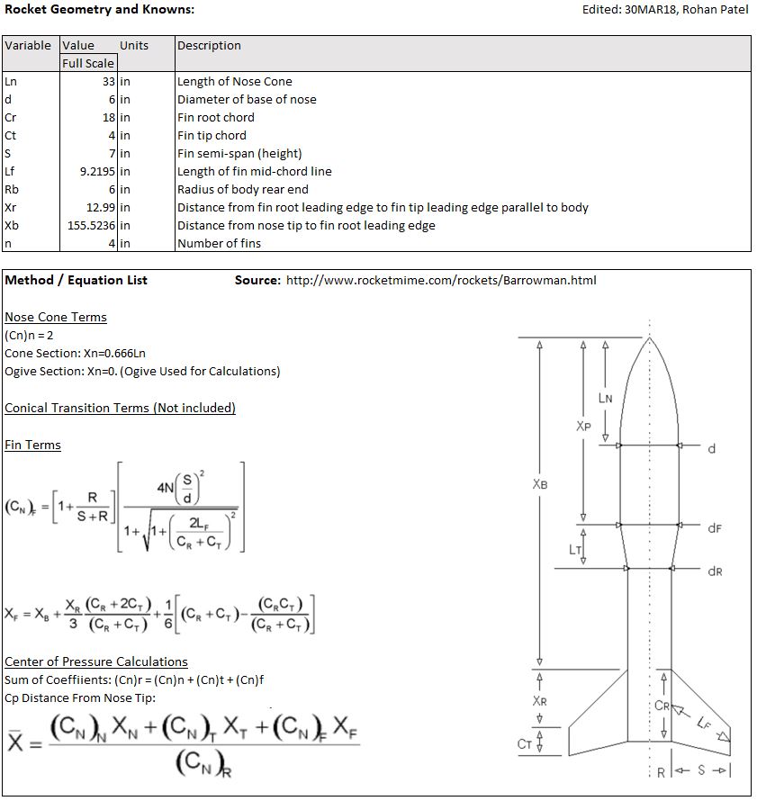
| Xn = 15.378 | (CN)F= 13.80997 | XF= 163.7621 | CN= 15.80997 | X= 144.9912 |
Using the Barrowman equations, I found that the approximate center of pressure is located 145 inches below the tip of the nose cone. This theory was used to check OpenRocket’s 123 inch CP position prediction. The Barrowman equations are more general and do not account for weights which make them a bit less accurate. The equations were used anyway to verify stability with an alternate method.
4.0 Subscale Tests
The first subscale test was conducted in December 2017 and resulted in a partially successful flight. The vehicle was not loaded with AP, had a single GPS, and a dual recovery system. Fin sizing was a incorrect leading to launch vehicle instability and unexpected performance. After the rail, the vehicle continued upward for roughly six seconds before beginning to tumble. We were fortunate enough that the parachutes deployed safely and the rocket made a smooth landing. After the incident, our adviser told us to switch to a four fin design and rework the geometry. Our biggest issue was a lack of communication to keep the OpenRocket model up to date. Looking back at the file, we recognized incorrect weight estimations and inaccuracies in our model which led us to believe the rocket was stable when in reality it was not.
The second subscale test was done in March 2018 which resulted in a nominal flight. The rocket performed perfectly and was flown with AP propellant. It reached the targeted 10,300 feet apogee and drifted away into the Mojave desert. For this launch, we did not equip the rocket with a GPS system because of the AP grain. It was sadly lost but relayed flight data that we wanted to see. The test was the green light for the fullscale vehicle.
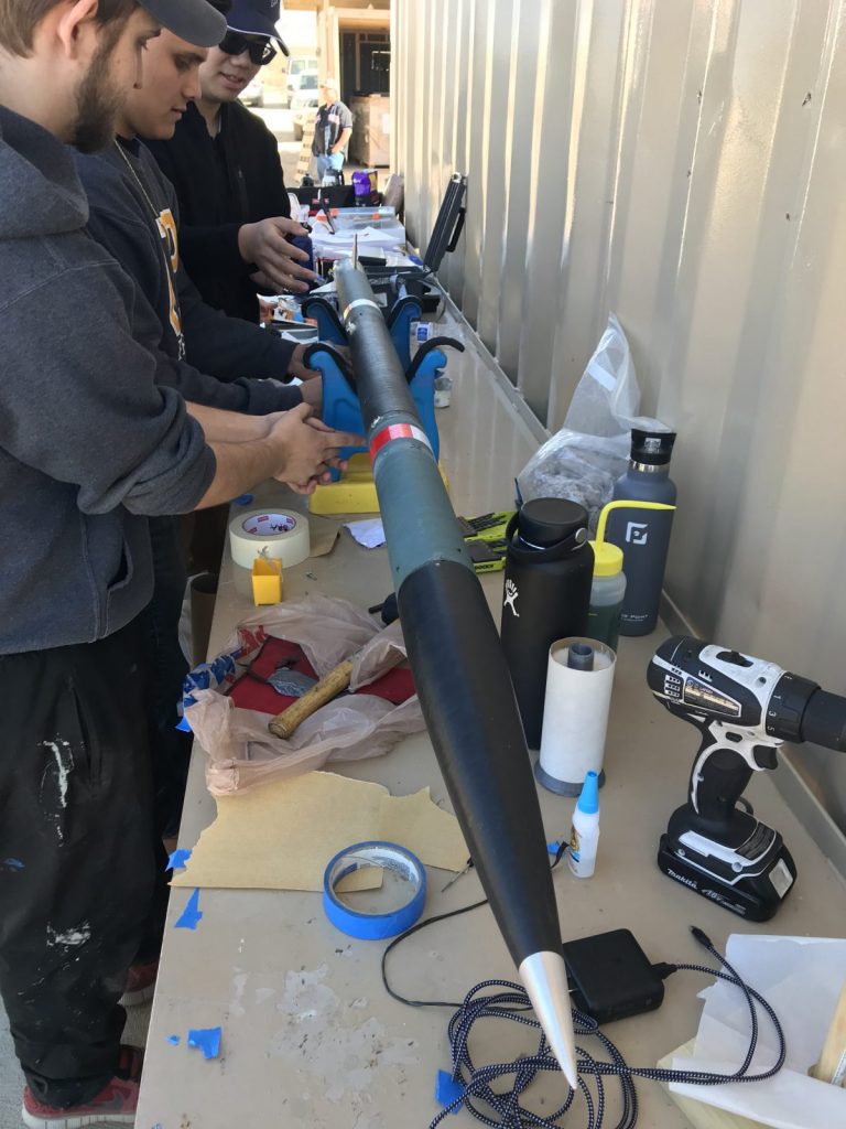
5.0 Building The Fullscale Rocket
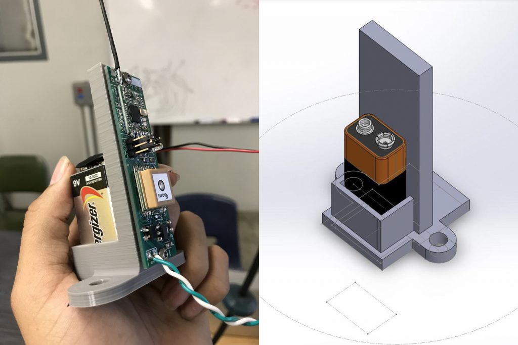
The GPS Sled
Aerodynamics was also responsible for the nose cone internals. I designed a quick mounting solution which would keep our eggfinder GPS unit and a 9 volt battery power supply upright in the cone. This would be bolted down with the U-Bolts that protrude through the bulk plate. The design changed once to use less filament and the final design (as seen on the left) was printed using PLA. This was a quick part of the build.
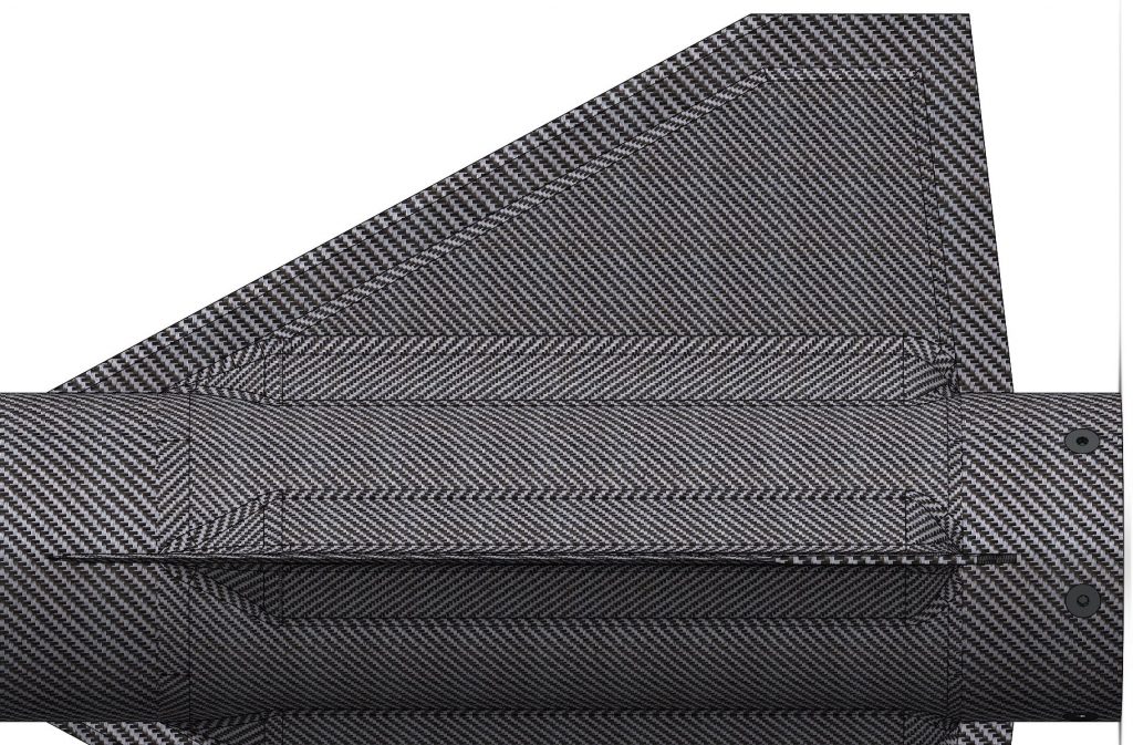
Fin Construction
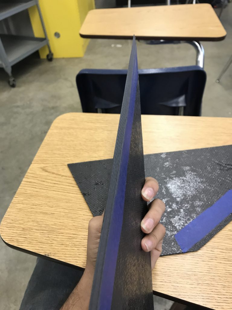
The fins were manufactured out of carbon fiber mixed with epoxy. Our original idea was to use Al6061-T6 aluminium and make the fin can out of the same material, but this idea was scrapped due to high costs and uncertainty of delivery. The set of four fins stand 7 inches tall, have a chord of 16 inches, and a sweep angle of roughly 30 degrees. I beveled the fins to a 30 degree angle in order to prevent stagnant airflow at the leading edges. This was done by some geometry, tape, and a very useful belt sander. The photo on the right shows the beveled edges and tape guide lines I used. Three of the fins cured perfectly, but the last one became known as the “noodle” fin. It wasn’t rigid and this was the underlying reason our fin can extended up to 6 inches of the 7 inch height of the fins.
I learned that it is one thing to design and engineer something; and it is another to actually make it. There were inconsistencies in fin thickness and sizing sometimes as high as 0.1 inches! My team and I found ways to fix this issue by sanding and updating our models. Throughout the process, I have gained respect for the manufacturing process and the differences that occur between designing and actually making something.
Preparing the Fin Mount Assembly
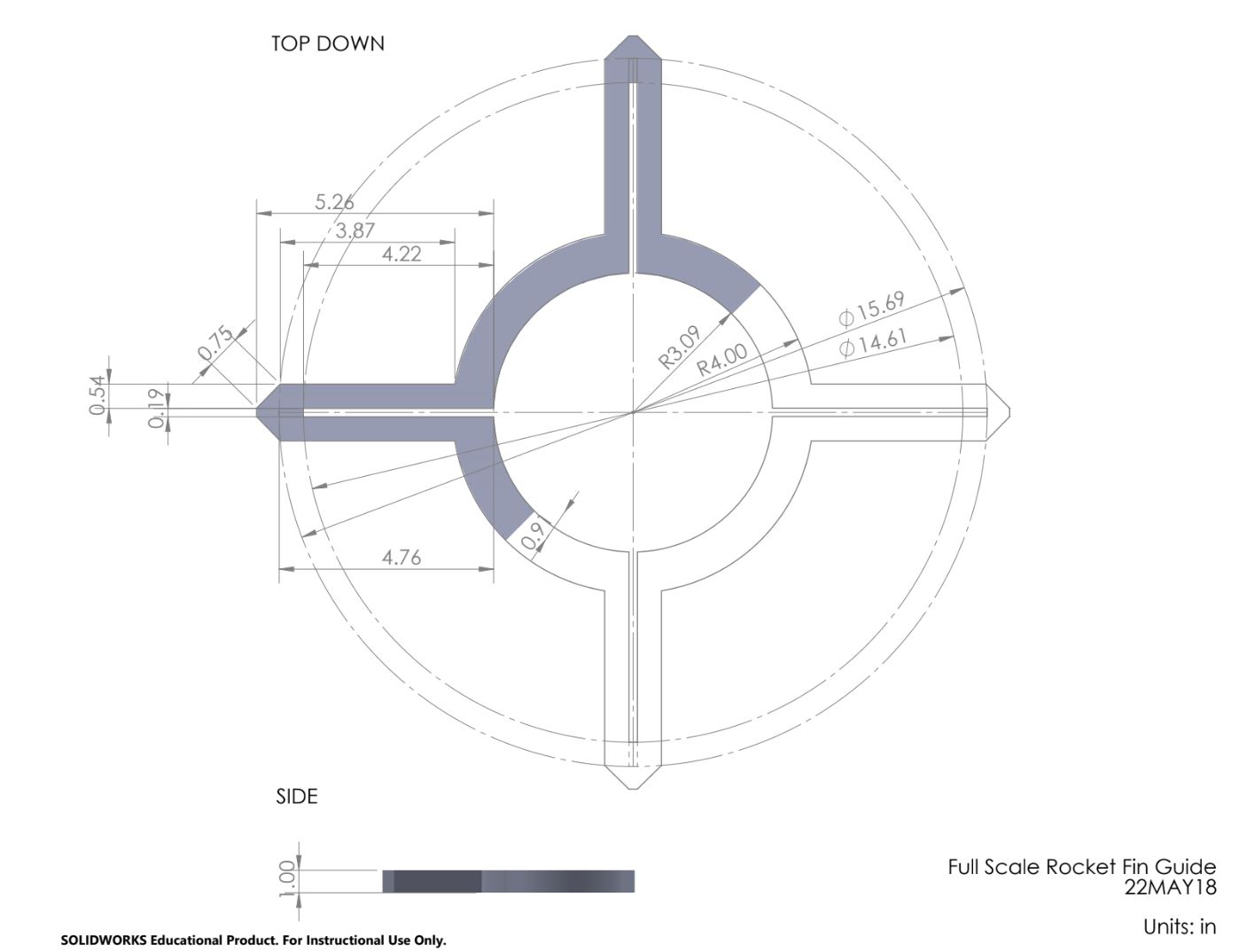
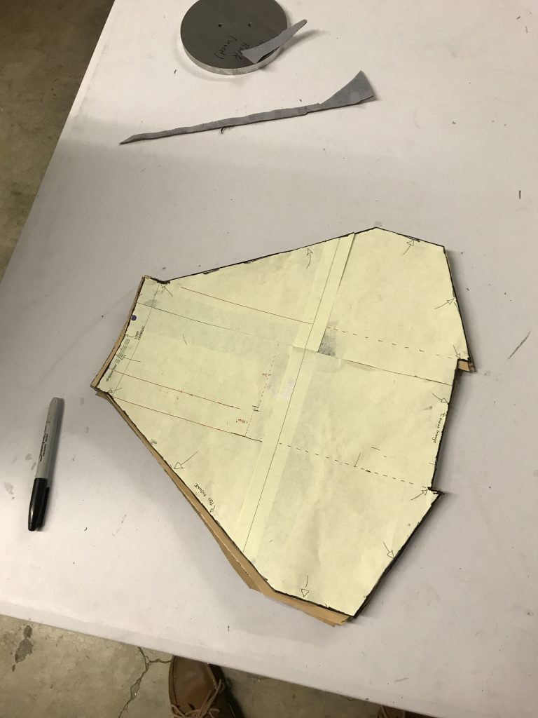
In order to mount the fins as accurately as possible, I opted to design and have cut a fin guide that would fit at a fixed position on the fins in order to be mounted accurately. At mach speeds it is critical that the fins be mounted as accurately as possible to not induce a roll. My approach to this was to make guides that we can slip on and off the body in order to position and epoxy down the fins. These can be broken off after use.
Mounting and Finishes
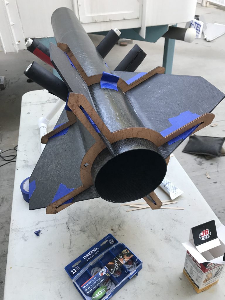
The Mount Assembly was cut out twice and used for the forward and aft sections of the rocket. I planned for them to be about 9 inches deep into the chord and around 15 inches deep. The image on the left shows all the fins positioned using the guides. The fins were later JB welded down before we began the fin can.
The fin can was designed to be three sheets of epoxy mixed carbon fiber per side which would extend out to one inch below the edges of the fin. Below is a photo of the guide I made with the uncured carbon fiber wrap under it. These plates of carbon fiber would be cured directly onto the rocket.
Small 3D printed triangular prisms and tetrahedrons were printed as well to support the fins and the can. I was aware that the temperatures will be higher than the 3D print max. allowable temperature and so we used JB weld to cover over these pieces to ensure that aren’t exposed to the external flow. The fin can layers (seen on the left) were stenciled and cut out. They would cure on top of the rocket body itself so it can take the shape of the fin, prism, and body. The can design was quite unique but it was needed because we couldn’t have our aluminium can parts CNC’d in time.
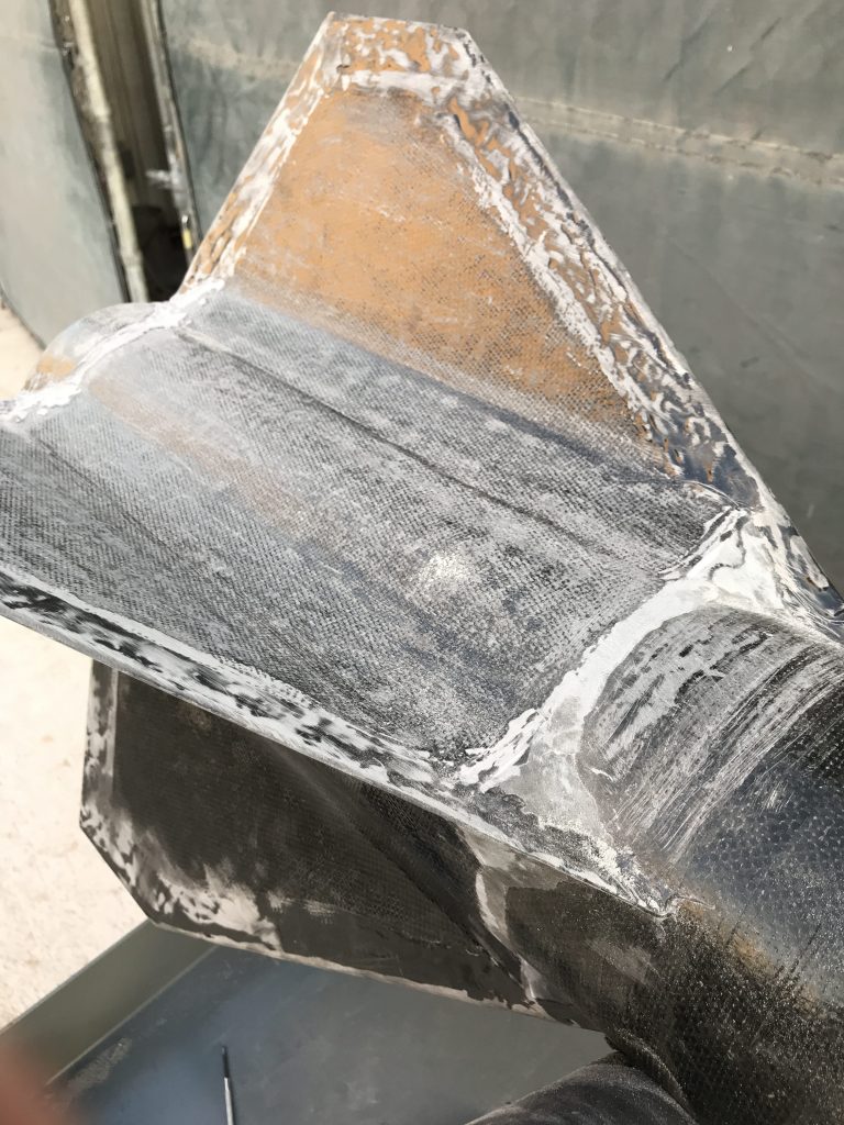
After the prisms were JB welded, the can sections hardened, the tetrahedrons were JB quicked, and the leading edges were treated with JB weld, it was time to start the tedious process of sanding down each and every surface of the aft section of the rocket. The sanding process took a pain staking 10 hours over the course of two days using up nearly 5 sheets of sand paper. I first used an orbit sander for most of the large surfaces, then opted for a sand tip dremel for the fine corners and edges. Finally, it was just my hand and good old fashion sand paper to finish it off. This entire part was quite laborious but with good music, it was completed. The fins now were ready to be painted.
After the sanding process, my work was officially completed. I handed over the body to the rest of the team for painting and touch ups, and helped out with other tasks that needed to be completed. A couple days before the journey to New Mexico, I remember we were in the lab till 3:30 in the morning. With good music and company, it wasn’t an issue at all. There was still much work to be done but the team was quite dedicated.
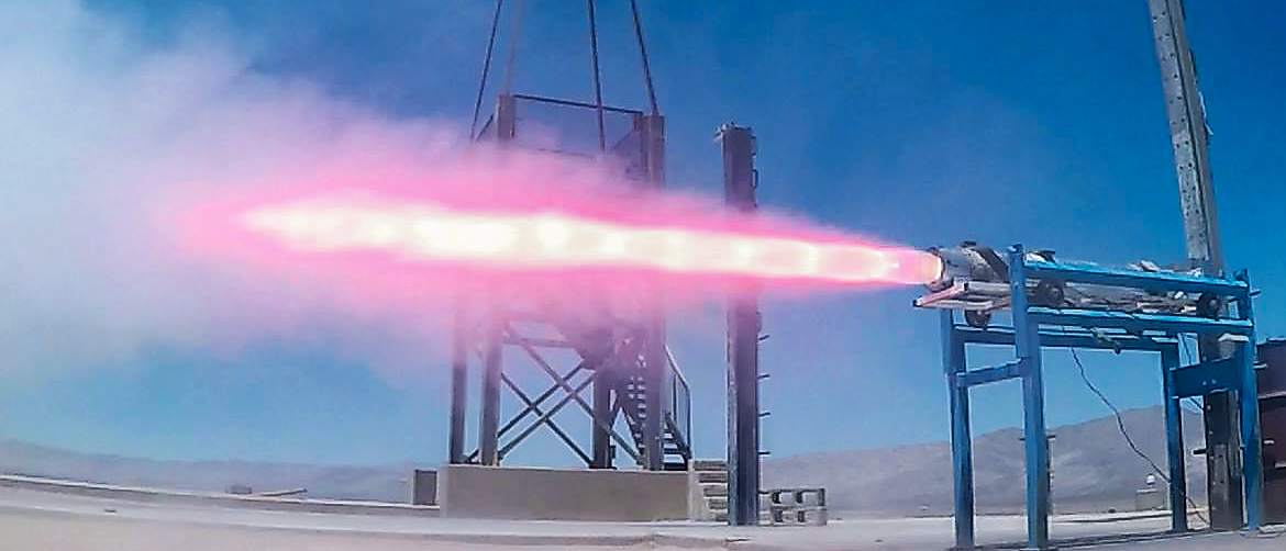
The Saturday prior, we conducted an static fire of our custom engine. Behold 2100 pounds of peak thrust and 1800 lb of sustained thrust. This beautiful sight proved to be quite deadly for our rocket during the launch.
6.0 Fullscale Launch
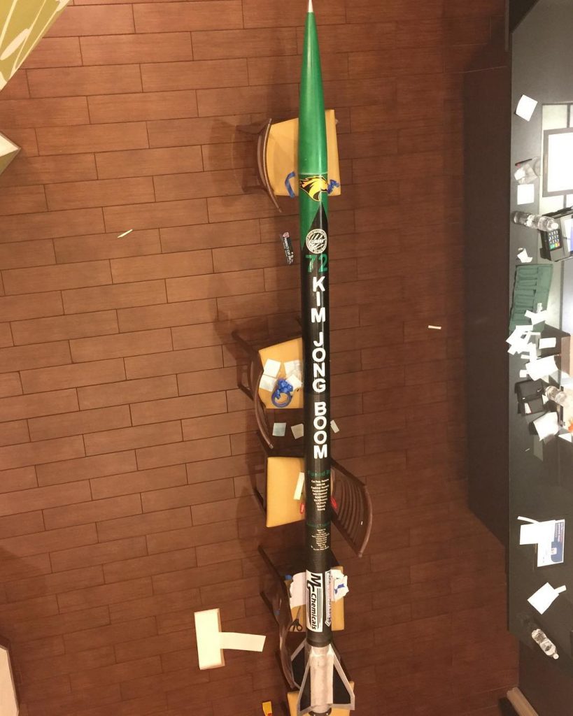
The completed rocket stood 14.7 feet tall and had our school’s logo, our team logo, name, and sponsors pasted on.
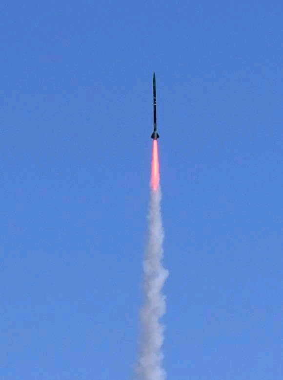
On June 23, 2018 at around 2:00 PM the affectionately named “Kim Jong Boom” lifted off the ground. The ascent trajectory was nominal and the rocket climbed to over 10,300 feet without any visual issues. After burnout, the rocket finally gave way at its maximum velocity and highest point of dynamic pressure.
So what happened?
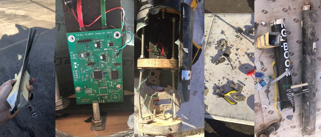
In short, the fins and vehicle structure was not built to withstand the speed that the engine produced. As mentioned previously divergence became an issue after mach 2.0 and flutter would occur at or above mach 2.4. The upper section of the airframe tumbled over and the engine section continued ascending. Luckily some parts were found and the SpaceX board was saved. The fins sheered off most likely due to the immense amount of energy in the system at the maximum velocity of the vehicle. Flutter is an incredible phenomenon that needs to be well understood. I am sure that when I design another rocket, I will pay closer attention to the flutter characteristics. While the motor performed out of specification, it is still important to thoroughly understand how the rocket broke apart.
Flight Statistics:
| Max Velocity
2978 ft/s |
Mach
2.7 |
Time to “Apogee”
5.35 seconds |
Avg. Accel.
16.52 G’s |
Last Rec. Alt.
10,310 feet |
7.0 Conclusion
Overall, despite the launch outcome, I was very proud to be apart of such an incredible team. Not only did we build two very powerful rockets, we all learned a lot about rocket design, manufacturing, and working together. Personally, the wealth of knowledge I attained and the friendships I made throughout these nine months made the entire experience well worth the late nights and tireless effort. Learning about aerodynamics, engineering versus manufacturing, and being flexible with the design were a few of the most important lessons I learned throughout the process. Divergence and flutter are two VERY important aspects to consider as an aerodynamicist! Thanks to the incredible leads, Nelson Ho and Drayton Lieske, for being supportive and taking the time to teach. I had a great time and look forward to carrying this enthusiasm over to the next year as a member of Liquid Rocket Lab and as a returning member of the IREC team.