Mission Design Lead and Systems Engineering
Contents
- Introduction and Summary
- Concept of Operations
- Mission Design
- Trajectory Design
- Launch Opportunity and Vehicle
- Cost Estimation
- References
1.0 Introduction and Summary
From November 2019 to May 2020, the team I was apart of and I have been involved in a solar gravitational lensing spacecraft design. I lead the trajectory and mission design, and was involved with the systems engineering process. I have only included the parts that I was involved with on my website. It is important to note that some contents of the proposal are sensitive and have been removed from this webpage.
Solar gravitational lensing (SGL) is the process of using an Einstein ring formed around the Sun to magnify stars and planetary systems behind for observation. This process will allow scientists to study the orbiting exoplanets in far greater detail than current Earth-based observations. First a star system needs to be chosen and its astronomical state (right ascension and declination) at the expected observation date needs to be determined. Star systems can be narrowed down by number of known exoplanets, distance from the Sun, and their declination angle. Once a target is chosen, the opposite right ascension and declination angles are determined and a point in space is created ~550 AU away. For the context of an undergraduate preliminary study, it was determined to not remove any tangential velocity components thus approximating the observation to a single point instead of a radial line from the Sun. The mission design and optimization of the trajectory now target this point and the goal is to reach it as soon as possible with the constraint of using currently available technology. This last factor greatly limited the scope of the trajectory design options due to the vast distances needing to be covered. The short description on SGL doesn’t quite do the science behind it justice, but serves as a background for the mission.
In all, this senior design mission concept has taught me quite a bit more than a conventional classroom project. Below is a list of programs and topics I used in the process:
- STK (creating end to end flybys from optimizer data, finding coverage from DSN stations and points of interest, occulations, solar conjunctions, B-Plane targeting, custom report generation, astrogator mission sequence creation, visualizations and data exporting)
- MALTO (Low thrust trajectory design, experience with the optimization process and tweaking inputs for convergence, parametric studies to generate launch windows and performance estimations)
- MATLAB (perijee dispersions errors, custom scripts and functions used for data processing of the broad search data, trajectory, and mission)
- NAIF SPICE Toolkit (SPK file loading, querying, data generation from saved .bsp files)
- Excel (Mission planning from exported data from MALTO based on power)
- NASA PCEC (Project Cost Estimation Capability: Estimating costs for the vehicle and project)
I appreciate the help from my team for their hard work and cooperation on this spacecraft design, and I also would like to thank my advisor Dr. Navid Nakhjiri for his continued insight and support. Special thanks to Try Lam and Dr. Damon Landau from JPL for their help with the broad search and questions I had using MALTO. Overall, I had a great time working on this project and have learned quite a bit into what it takes to design and manage a spacecraft program.
2.0 Concept of Operations
The Voyager III mission will begin in late 2044 with a Space Launch System (SLS) Block 1B launch and heliocentric orbital injection. After a systems checkout period, RETRIEVER will begin a low thrust burn to increase its heliocentric energy in preparation for the Earth flyby. During the interplanetary orbit and Earth gravity assist, which occurs in 2047, the spacecraft can conduct science and can calibrate its onboard instruments. After another checkout period, RETREIVER will then restart its low thrust engine and head towards Jupiter in 2048 for another gravity assist, offering imaging science of the Galilean moons. A long duration low thrust burn, which will deplete all remaining propellant, will be conducted after the flyby and RETRIEVER will be sent to the interstellar medium. Additional science will be conducted along the way and periodic equipment exercising and communication will commence. After 58 years from launch, RETRIEVER will finally reach the solar focal line and image the TRAPPIST-1 exoplanet system. The data will be sent to Earth, and the possible extended mission and disposal protocol will begin. Figure 2.1 summarizes the critical phases of the mission in the order they will occur in.
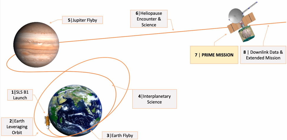
Figure 2.1 Concept of Operations for the Voyager III Mission
3.0 Mission Design Summary
The project is simulated to have passed the Preliminary Design Review (PDR). The next milestone is the Critical Design Review where detailed analysis of each subsystem and project element will be reviewed. Figure 3.1 illustrates the NASA project life cycle timeline in terms of project phases and technical reviews. Phase B is completed as of PDR and now Phase C will begin. Certain fabrication elements will be coordinated and the design will be finalized.
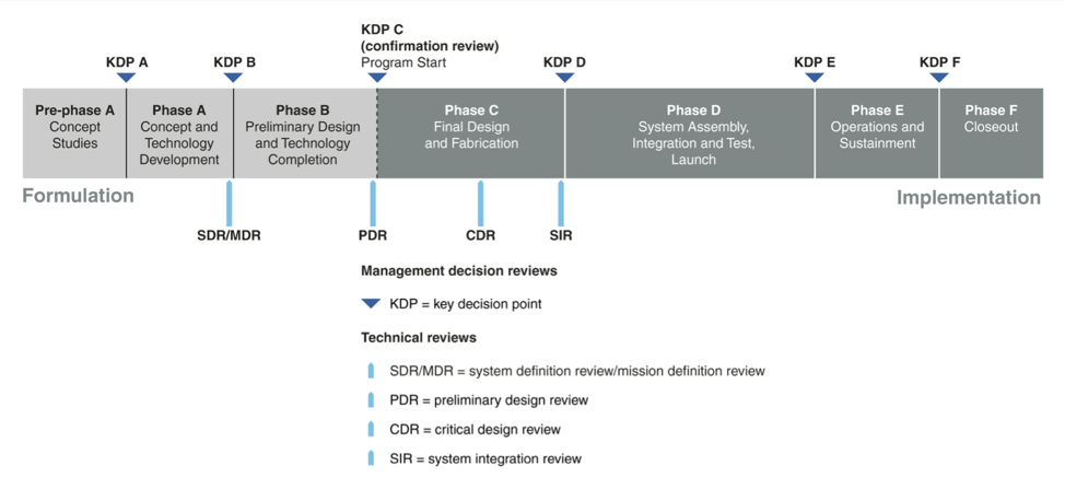
Figure 3.1 NASA Spaceflight Project Lifecycle [1]
Figure 3. 2 highlights key events of the mission design to their radial distances and time. The anticipated launch period is between August 4th and August 23rd. After second stage cutoff from the SLS and a nominal heliocentric orbit injection, the vehicle will be oriented for ground acquisition of signal. Once done, the radiator panels and magnetometer boom will extend and the systems checkout period will begin. A trajectory correction maneuver (TCM) will be performed on the attitude control system to correct for any launch injection errors. The first low thrust burn will begin and routine uplinks and downlinks with the spacecraft will commence. The burn will finish in June of 2045 and a 2 month coast period will begin. Interplanetary and parallax science can be conducted in this window. There is a solar conjunction occurring on July 19, 2045 for 19 hours and 16 minutes. Any thrusting or TCMs are prohibited out of line of sight (LOS) due to a lack of ground intervention in the event the spacecraft goes into safeing. The second burn will be conducted up until the pre-flyby forced coast period for planetary protection. A TCM will be performed and the Earth flyby will yield a valuable opportunity to calibrate the telescope and other science equipment. After the flyby, the low thrust engine will be restarted and a short coast period to Jupiter will begin. The Jupiter flyby will be preceded by a TCM, and scientific instruments will be reactivated to collect data on the environment and Jovian moons through the flyby. On the solar system escape portion of the trajectory, the low thrust engine will be restarted and after 10 AU (radial distance from the Sun) the second major interplanetary science mission to investigate the Extragalactic Background Light (EBL) will begin. The spacecraft will routinely exercise its reaction wheels and instruments onboard and relay engineering data via the low gain antenna (LGA). Another scientific mission opportunity will be realized at the heliopause and data will be transmitted via the high gain antenna (HGA). From the heliopause (100 AU) to the solar focal line (550 AU), the spacecraft will enter a long duration low power cruise with minimal ground staffing. Periodic engineering data will be transmitted via the LGA and equipment exercising will be done. In preparation for the prime mission, the attitude control system will be tested and verified. Data will be relayed to Earth and the telescope will begin another calibration phase. The prime mission is expected to take 30 days beginning in August of 2102. After the prime mission the data will be relayed via the HGA for roughly 0.7 years. Any extended mission opportunities will be conducted after. System disposal is not prioritized by any planetary protection regulations as the spacecraft is already on a solar system escape trajectory. The legacy of the existing Voyager missions can be continued on RETRIEVER with another golden plaque representing humanity to those out in the interstellar medium.
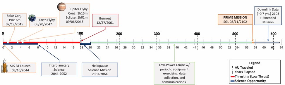
Figure 3.2 Mission Timeline
4.0 Trajectory Design
The primary goal of the trajectory design is to be able to target and fly past a specific point in space directly opposite of the TRAPPIST-1 star system with respect to the Sun. This point would have a fixed radial distance from the Sun of 550 astronomical units (AU) and would be oriented in space with a specific right ascension of 166.62 degrees and a declination angle of 5.04 degrees with respect to the Mean Ecliptic J2000 reference frame. The trajectory accuracy must be within 1 km by 1 km, as requested by the RFP issuer.
Another key objective of the trajectory design is to maximize the solar system heliocentric velocity in order to reach the solar focal line in a reasonable time. Current concepts to achieve escape velocities in excess of 12 AU/year include: large solar sails flown close to the Sun to leverage solar radiation pressure, and the option to use a large ΔV maneuver, on the order of 5-8 km/s, very close to the Sun (~0.04 AU) [2] in order to utilize the Oberth effect [3]. While these concepts yield times of flight under 50 years [2], they rely on low TRL technology and mission design practices not yet conducted. The thermal considerations, required solar sail area, and maneuver design accuracy shortcomings are some of the setbacks. Therefore, a more conventional approach was utilized. Planetary gravity assists can help boost the spacecraft’s velocity post flyby, but still a significant amount of ΔV is required. Therefore, a low thrust, long duration burn trajectory was considered for this mission design. By combining classical interplanetary trajectory design with flight proven Hall Effect engines, this mission is potentially viable at the expense of a long duration.
4.1 Broad Search
A multi-gravity assist, broad trajectory search was conducted before the optimization process to find possible flybys that would maximize the solar system escape velocity. This data was provided by the Jet Propulsion Laboratory’s broad search algorithm named Star. Lambert arc fits would be used to join multiple bodies. Each leg would have discontinuous endpoint velocities, but a ∆V is assumed to be applied by an optimized flyby. Trajectories are forward and backwards solved to reduce the number of tree nodes, and individual legs are grouped by date characteristics and velocities to reduce the computation time [4]. Table 4.1.1 summarizes the input and outputs regarding the broad search.
Table 4.1.1 JPL Star Broad Search Criteria and Results
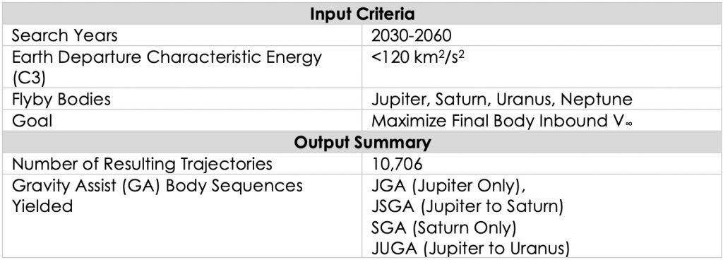
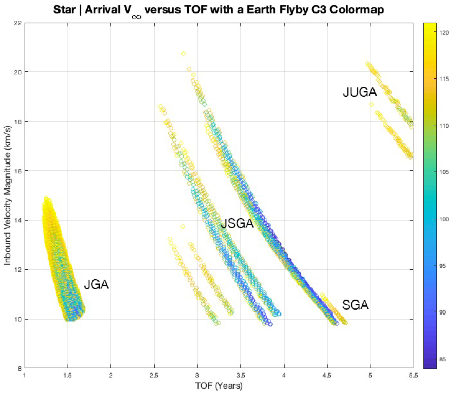
Figure 4.1.1 Star Results Sorted by TOF, V∞, and Earth Flyby Energy
Figure 4.1.1 plots the resulting trajectory possibilities by their time of flight, inbound relative velocity, and the required Earth departure characteristic energy. The search yielded several sets of gravity assist combinations which were traded based on their inbound relative velocity (V∞), right ascension of the final body at the encounter, maximum achievable turn angle (assuming a planar flyby and close approach altitude no less than 5000 km), and the encounter year. The Saturn only gravity assist trajectories were immediately dropped for their maximized Earth departure C3 and their low V∞ values. In the search, three different candidates were analyzed for preliminary investigation: a JGA with the Jupiter encounter in January of 2048, a JSGA with the Saturn encounter in November of 2059, and a JUGA with the Uranus encounter in 2039. The JSGA and JUGA trajectories offer higher inbound V∞ values of 20.73 and 20.35 km/s respectively compared to the 14.03 km/s from a single Jupiter flyby. This, coupled with the fact that the spacecraft can potentially collect more science data through additional planetary flybys, made these options more attractive in the beginning. However, there were certain limitations in these flyby body candidates. Both GA combinations had post flyby right ascension differences, with respect to the target, of greater than 11 degrees. This meant that the low thrust propulsion system would have to change the direction of travel and boost the heliocentric velocity of the spacecraft, resulting in a slower burnout velocity. Also, a more aggressive design and manufacturing timeline would be necessary for the JUGA trajectory as it encounters Uranus in 2039. This means that the Earth launch would have to be in the late 2020’s in order to accommodate for ΔV leveraging flybys and the transfer to Jupiter. Subsequently, the JSGA opportunity encounters Saturn, which is only roughly 9.6 AU from the Sun, in 2059. With these considerations, and the fact that the launch period becomes much more sensitive to the multi-flyby mission design, a Jupiter only gravity assist trajectory selected for optimization.
It is important to note that despite only being roughly 5 AU from the Sun, Jupiter’s offset from the required heliocentric outbound right ascension is significant enough to account for in the broad search trajectory selection. Of the nearly 8,800 Earth-Jupiter opportunities, two had post flyby heliocentric right ascensions that matched the target conditions. Figure 4.1.2 displays these two opportunities and their differences in the required post flyby right ascensions after a 20 year propagation.
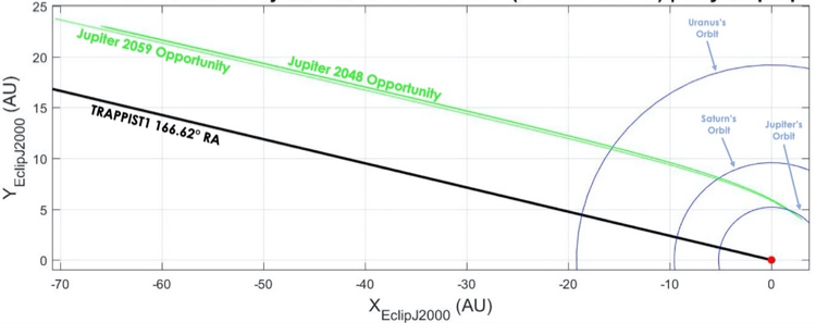
Figure 4.1.2 Selected JGA Opportunities from Broad Search
The calculated offset, in order to intercept the SGL point, from Jupiter was 0.4798 degrees (resulting in a searched right ascension of 167.099 degrees for all prograde trajectories). These two opportunities were within 0.015 degrees of this new target. The 2048 JGA opportunity was then selected for the low thrust optimization portion of the trajectory design due to its earlier encounter year.
4.2 Low Thrust Trajectory Design and Optimization
The trajectory optimization process began with an investigation into the current capabilities of electric propulsion engines. Hall Effect thrusters were considered due to their increasing efficiency, nearing 60%, and output thrust, in excess of 0.4 N [5]. All candidate trajectories were designed with the output thrust as the driving propulsion parameter, and it was preferred to exhaust the propellant as soon as possible after the Jupiter flyby as this would reduce the amount of time the power system would have to deliver the large input power.
The Jet Propulsion Laboratory’s Mission Analysis Low Thrust Optimizer (MALTO), which is a preliminary mission design tool, was utilized for trajectory optimization. It models low thrust arcs as a series of impulsive maneuvers segments, and patches together the trajectory by forward and backwards propagating from control points. Control points can be either planets or defined points in space given the orbital elements, valid times, and reference body.
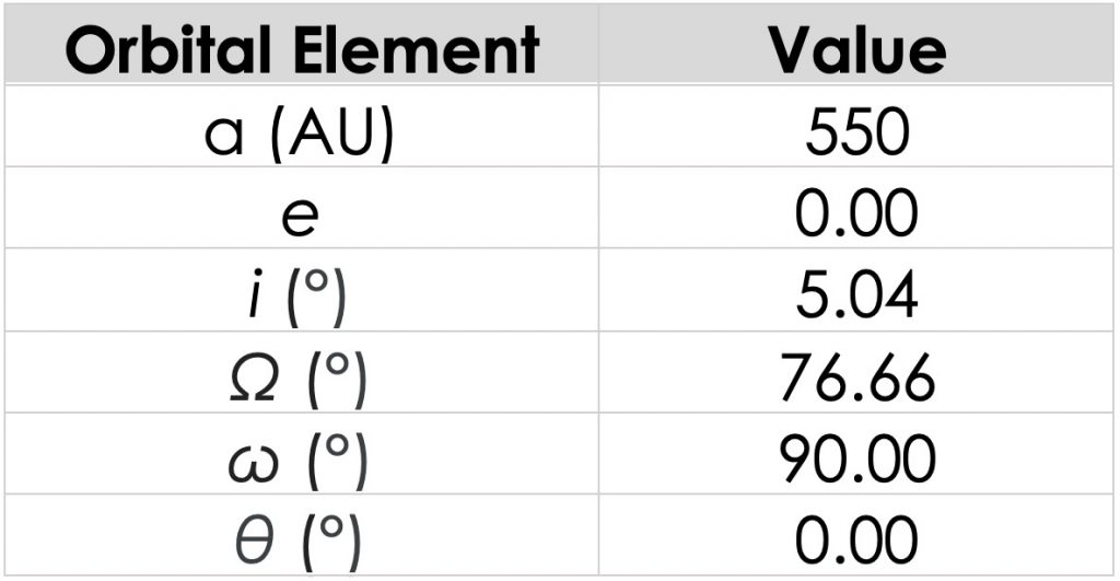
The broad search found the Earth to Jupiter (EJ) portion of the trajectory at the maximum C3 (120 km2/s2). This direct transfer would be possible on deep space launch vehicles, but the mass delivered would be too small for the spacecraft design. The initial estimate for RETRIEVER was on the order of 2500 kg dry and in excess of 12,000 kg wet. Preliminary analysis into a STAR-37 kick stage was conducted to see if having a third stage could improve performance. However, after using the Tsiolkovsky ΔV equation, it was found that a kick stage could only deliver roughly 230 m/s which is not enough for the leveraging orbit injection. Therefore a ΔV-EGA trajectory that utilizes a deep space maneuver (DSM) and an Earth flyby, similar to that of the Juno Mission [6], was utilized. The advantage of this approach is that it only relies on Earth gravity assist(s), and so targeting specific flyby parameters is simplified. However, one significant limitation is that the spacecraft will be carrying nuclear substances and conducting these flybys. Mission implications and subsequent analysis for the EGA are discussed further on. A 3:1– Earth Leveraging orbit, discussed by Sims and Longuski in [7] was selected for this trajectory as it was a reasonable compromise between the amount of time spent interplanetary, and required launch energy. It is important to note that the analysis covered by Sims and Longuski are designed to rendezvous with Jupiter. RETRIEVER’s trajectory is aiming to maximize the incoming relative velocity. This means that it would be more optimal to use the 3:1– as a starting point and let the optimizer build heliocentric energy by running the electric propulsion engine during the EJ transfer to maximize the incoming heliocentric velocity. The only limitation in this was the derived requirement for mandatory forced coast periods before and after flybys for planetary protection and to prevent powered flyby maneuver errors. These considerations were applied in the MALTO trajectory, and the deep space maneuver would be replaced by a long duration low thrust burn to prevent the need of carrying a kickstage. The final portion of the trajectory was targeting the correct heliocentric right ascension and distance. A user defined control point in space was created with the following Keplerian orbital elements in Table 4.2.1.
Table 4.2.1 TRAPPIST-1 Observation Target (Mean Ecliptic J2000 from the Sun)
Ultimately, the vehicle mass was capped at 14,000 kg wet. After an extensive trajectory optimization period and tweaking date and mass limits, the trajectory converged. With the tolerances, the largest trajectory discontinuity between matchpoints in the position was 0.05 km and the largest velocity discontinuity was on the order of 10-9 km/s. Table 4.2.2 provides a summary of all various trajectory parameters.
Table 4.2.2 Trajectory Encounter Summary
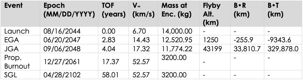
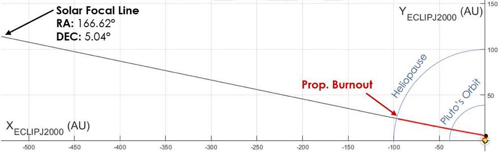
Figure 4.2.1 Entire Trajectory (Mean Ecliptic J2000 XY View)
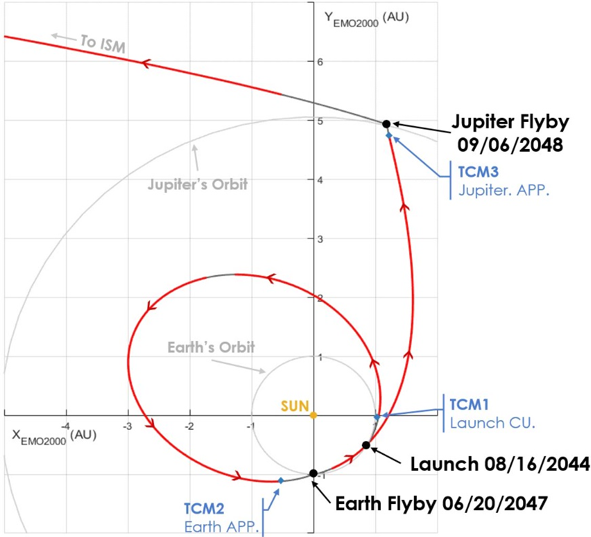
Figure 4.2.2 Interplanetary Trajectory (Mean Ecliptic J2000 XY View)
Figure 4.2.1 displays the entire trajectory. Notice that the propulsion burnout occurs near the Heliopause at roughly 97 AU. Figure 4.2.2 contains the interplanetary portion. Arrows are added to follow the direction of the spacecraft. The first low thrust burn occurs shortly after launch and the first clean up trajectory correction maneuver (TCM). The Earth leveraging orbit requires thrusting as a chemical deep space maneuver is not executed. There is a break in thrusting momentarily, and this can be used for additional science experimentation. Also the thruster restart post JGA is delayed for an additional science opportunity. There are regions of the interplanetary trajectory where the spacecraft is restricted from thrusting. As mentioned earlier, these are forced coast periods added to ensure the flybys would not be powered to reduce state errors post flyby and for planetary protection. Additional TCMs are added before the EGA and JGA which were assumed to be <2 m/s as per [6]. There are four main engine burns that are summarized in Table 4.2.3.
Table 4.2.3 Low Thrust Burn Schedule and ΔV
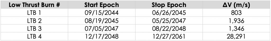
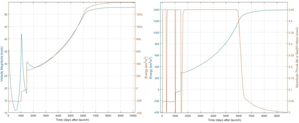
Figure 4.2.3 Heliocentric Velocity, Energy, and Thrust Magnitude versus Time
Figure 4.2.3 shows the heliocentric velocity and energy as well as the thrust required versus time. The blue spike around 1000 days on the left hand plot is the Earth gravity assist, and the second is the Jupiter flyby. It is important to note just how dependent the trajectory is on propulsion system that can run for long durations and provide relatively high thrust (seen on the right side plot). The expected heliocentric energy will be roughly 1400 km2/s2 which equates to 11.08 AU/year.
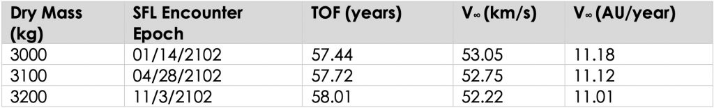
RETRIEVE’s dry mass was varied in optimizations between 3000 kg to 3200 kg as the mass of the spacecraft grew. The maximum available thrust was set to 0.45N, which is 0.15 N less than the maximum output of the Busek BTH-8000 at 8kW input power for contingency. The trajectory can also withstand a missed thrust day for every one hundred days of operation by MALTO’s missed thrust definition. Table 4.2.4 contains trajectory parameters as the dry mass was varied.
Table 4.2.4 SFL Arrival Sensitivity to Dry Mass (Assuming fixed wet mass of 14,000 kg)
The trajectory discontinuities were deemed acceptable as MALTO is a preliminary mission design tool. While it is powerful in its capability, MALTO has underlying assumptions built into its astrodynamics computation making it useful for rapid prototyping of trajectories. The trajectory would need to be further developed in higher fidelity applications such as JPL’s MYSTIC. For this reason, the trajectory cannot be guaranteed at this point of the analysis to meet the RFP issuer’s 1 km by 1 km trajectory accuracy at the solar focal line. Orbit determination uncertainties are likely to be greater than this limit and so, for the scope of this investigation, the accuracy was forgone.
4.3 Trajectory Coverage and Analysis
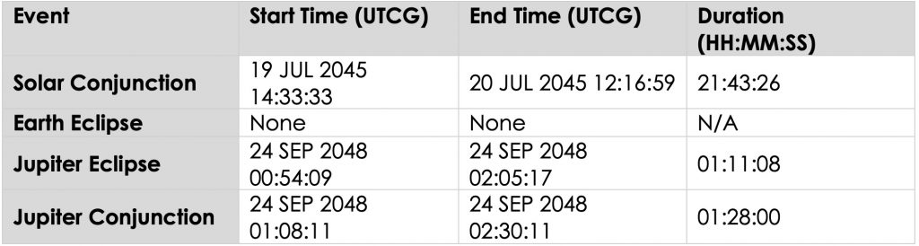
With a converged MALTO solution the next goal for the trajectory design was to analyze the flybys in detail and check for occultations, eclipses, and solar conjunctions. Analytical Graphics Incorporated’s (AGI) Satellite Toolkit (STK) was used, and with the Astrogator extension, interplanetary trajectory modelling and SPK (Satellite and Planetary Kernel) file reading was accessible. Three scenarios were setup. The first was reading the generated position and velocity data from the MALTO produced SPK file to find the solar conjunctions that could occur along the entire trajectory. The second and third scenarios were of the Earth and Jupiter flybys. These scenarios began out of the planet’s SOI and used Astrogator’s Mission Control Sequence (MCS) to target the flyby B-Plane and epoch parameters (listed in section 6.2). Table 4.3.1 lists all the out of line of sight (LOS) coverage times and durations.
Table 4.3.1 Trajectory Out of LOS Summary
The trajectory design included supplemental preliminary analysis for the EGA as the spacecraft is going to carry nuclear substances through the flyby. The Cassini mission, which contained 78 kg of plutonium, underwent extensive scrutiny by the public and Congress for carrying these through its Earth flyby, and so mission designers had to conduct extensive analysis to prove minimal impact probability [8]. It was considered to replace RETREIVER’s EGA with other flyby combinations, but the <60 year TOF derived requirement did not allow for this. The flyby was restricted to an altitude that limited the spatial density of orbiting objects around Earth. Figure 4.3.1, originally from [9], plots different NASA robotic missions that conducted an Earth flyby and has RETRIEVER’s expected flyby altitude. By selecting 1250 km, the risk of hitting existing orbital debris is limited.
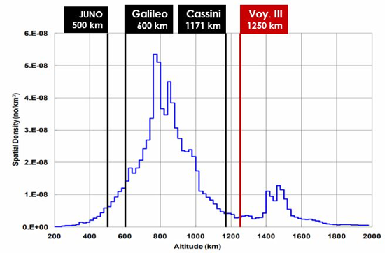
Figure 4.3.1 Earth Orbital Spatial Density versus Altitude [9]
The next method of supplemental analysis was introducing position and velocity errors from the deterministic trajectory before the flyby and propagating them out to perigee. This was done by first querying the state and epoch of the spacecraft roughly where it crossed Earth’s SOI (assumed to be 925,000 km). 3000 error samples were created with the assumption that 99.7%, or 3σ, of state errors were within a sphere 100 km in radius from the deterministic position, and 3.5 m/s from the velocity. To put these numbers into context, the original Voyager missions had a delivery accuracy of 100 km after 47.65 AU of travel [10]. The state errors are significantly exaggerated to determine the absolute worst case scenario as no existing data was found publicly regarding this topic at the time of analysis. Figure 4.3.2 plots the dispersion of the perigees. It is important to note that the mission would be most likely be compromised if the spacecraft were to fly at any of these extremes, despite having a low thrust propulsions system to correct the errors.
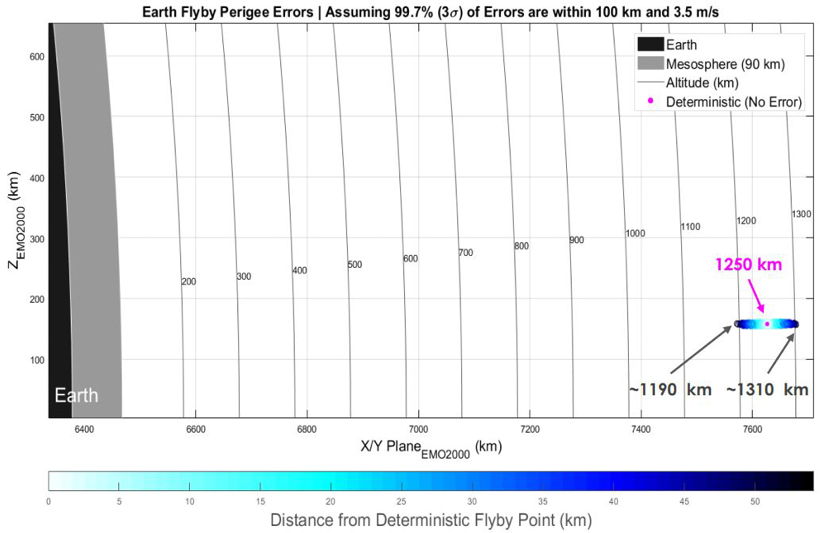
Figure 4.3.2 Earth Gravity Assist Perigee Error Dispersion
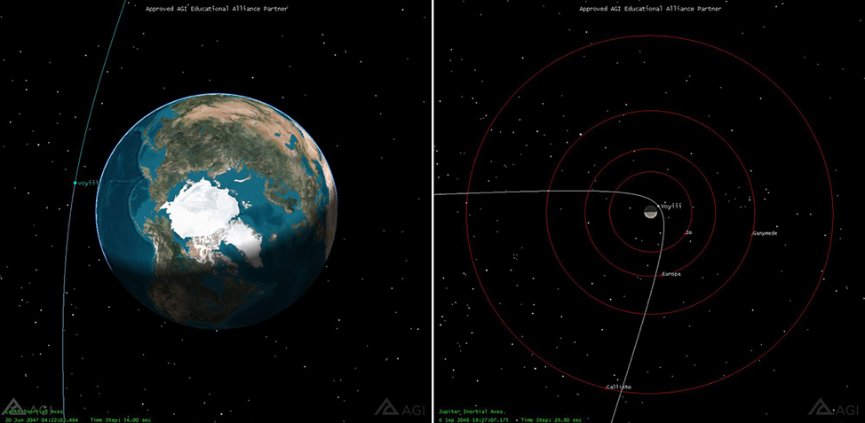
Figure 4.3.4 Earth Flyby (Left) Jupiter Flyby (Right)
Besides studying the interstellar medium and conducting interplanetary science, an additional opportunity for science was discovered in the trajectory analysis. The Jupiter flyby allows for the chance to study the Galilean moons. Table 4.3.2 covers the close approaches of each of the four moons.
Table 4.3.2 Galilean Moon Flybys
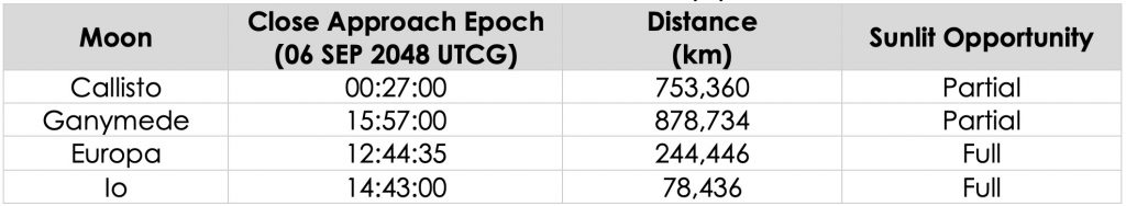
There is sufficient time between each close approach for reorienting the spacecraft for imaging and Io and Europa are prime candidates for a full disk image.
5.0 Launch Opportunity and Vehicle
The trajectory design and weight of the spacecraft significantly limited the available launch vehicles. Because of the time of flight derived requirement, the trajectory requires a high launch C3 of 44.89 km2/s2 (V∞ of 6.70 km/s). It is assumed that the launch vehicle will deliver this entirely in order to save the spacecraft’s propellant, and to not have to use a kick stage. Existing Evolved Expendable Launch Vehicles (EELV) like ULA’s Delta IV Heavy and Atlas V 551 were considered for their reliability and nuclear carrying capability. SpaceX’s Falcon Heavy in the recoverable and fully expendable configurations were also investigated due to their cost, but these vehicles are not nuclear rated and have only launched twice at the time of analysis. Finally, the NASA/Boeing Space Launch System (SLS) Block 1B and 2 were traded as these are heavy lift, assumed nuclear capable, vehicles designed for deep space missions with high launch energy requirements. Table 4.4.1 reviews the properties of the launch vehicles which were considered. Note that options such as Blue Origin’s New Glen, SpaceX’s Starship, and ULA’s Vulcan were not considered due to a lack of available data. Starship and New Glen could be prime contenders for this mission as they are intended to compete with the SLS for deep space heavy lift missions.
Table 5.1 Considered Launch Vehicles
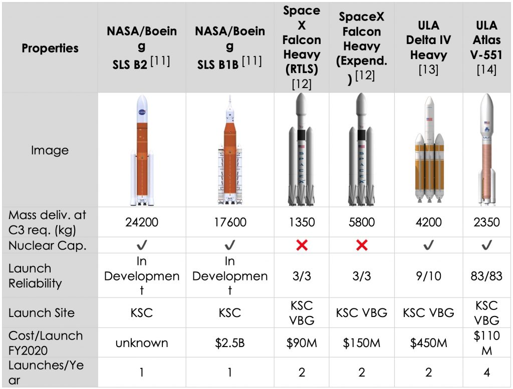
The SLS is expected to launch NASA’s flagships in the coming future such as Europa Clipper and few of the Artemis program’s missions. Despite the launch cost and development status, the SLS Block 1B was chosen as it is the only physical vehicle able to meet the mass and energy requirements. RETRIEVER can be comfortably accommodated in the B8.4m-27000 fairing due to its large 7.5 meter diameter dynamic envelope and over 18 meter tall fairing [11]. Also, the spacecraft and launch vehicle adapter is estimated to be <14,500 kg, allowing for a 3,100 kg mass margin. Once again, the private sector’s heavy lift deep space vehicles can likely be contenders for this mission, but due to their performance uncertainty at the time of analysis, they were not considered. The SLS Block 1B will launch RETRIEVER.
By parametrically varying the launch date in MALTO, a study was conducted in order to determine the launch opportunity and its effects on time of flight and required C3. Figure 5.1 illustrates the available launch opportunity for RETRIEVER. The time of flight derived requirement is also plotted to show the maximum bounds for the solution.
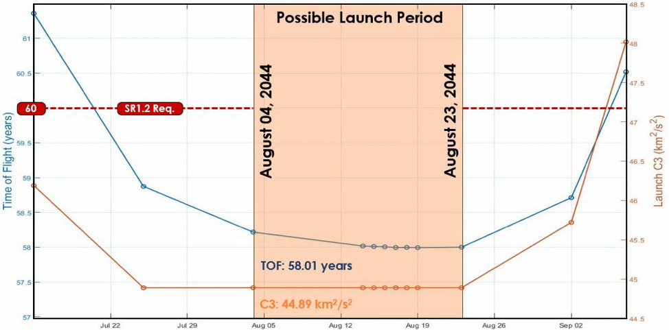
Figure 5.1 2044 Launch Opportunity
Based on the parametric results study, a launch opportunity between August 04 and August 23, 2044 was selected. It is expected that the launch date will be sensitive because of Jupiter’s heliocentric right ascension. The trajectory relies on Jupiter’s position in order to reduce the amount of propellant spent correcting the solar system escape leg’s right ascension.
6.0 Cost Breakdown
6.1 Projected Cost Estimation
Work Breakdown Structure (WBS) based component cost breakdowns were analyzed using the NASA Project Cost Estimation Capability (PCEC) tool. PCEC is designed to handle up to non-nuclear interplanetary missions, and so several assumptions and considerations had to be made in order to use the tool for this nuclear, solar-system escape mission.
The power system production cost for the flight hardware was estimated externally from PCEC as this was the nuclear component for the design. Operational cost for the reactor was estimated by PCEC’s end of life (EOL) model with the assumption that the total amount of power is what is required for the SGL mission, and not the total reactor output. This was done to ensure that the operations cost of the subsystem wouldn’t be tied to the nearly 10 kW of output power the reactor can provide. The NASA Glenn Research Center’s Kilopower reactor is an essential technology for this mission. To date, $20M have been allocated for a ground based 1 kW reactor prototype [15], but the development cost for a space rated version has not announced. It is expected that NASA’s Artemis program will include the development and use of the Kilopower reactor [16], but to be conservative, it was assumed that RETREIVER would cover this cost. Reference [17] was used to estimate the cost based off of data from Cassini’s GPHS-RTG and MSL’s MMRTG development. Kilopower utilizes Advanced Sterling Radioisotope Generators (ASRG) for its power generation, and it is included in the reference. It was assumed that costs for this technology type with the scaling factors from the legacy systems would be reasonable for preliminary analysis. Table 6.1.1 highlights the process used to estimate the development sum total.
Table 6.1.1 Estimation of ASRG Development and Manufacturing
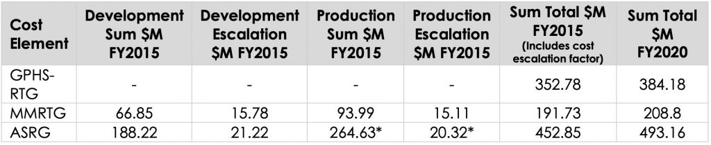
The asterisked numbers indicate estimates that were derived from the MMRTG’s development/product costs and factored into the ASRG development cost. This underlying assumption was made to approximate the total cost of $493.16M FY2020. The sum total was added to the flight system hardware cost. It is important to note that this is a preliminary cost analysis. Schedule overruns, or even cooperation with existing NASA projects may increase or decrease this development and manufacturing cost as it is a shared technology among future missions.
Other considerations and assumptions for the PCEC model include the total prime mission duration being limited to the SGL mission only, and the total accumulated radiation would be of the components inside the radiation vault. Miscellaneous costs were lumped into public and outreach, and reserve costs were not added as lumped percentages to the total cost. Figure 6.1.1 is the cost breakdown of the flight system. Note that the electrical and power distribution subsystem accounts for nearly 73.5% of the total cost, and this is an area for cost reduction. This is assuming the reactor development and integration costs as well as its operation through the mission.
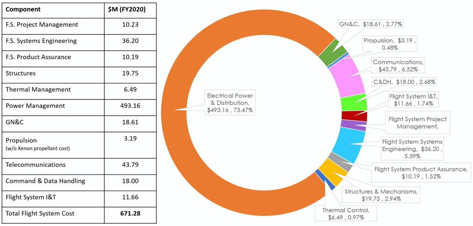
Figure 6.1.1 Total Flight System Cost Breakdown
Figure 6.1.2 breaks down the entire project cost estimation. Mission operations is clearly the largest cost in the model as it requires nearly $1.25 billion. However, it must be mentioned that this is estimated using PCEC’s cruise phase cost estimation component. This certainly can be reduced with limited communication with the spacecraft during its cruise after the Jupiter flyby. Periodic equipment exercising and state reporting can be done with the Deep Space Network, but further investigation into very long duration, low communication states need to be investigated. Finally, the operations cost can be further reduced by keeping a smaller number of staff to the project in the cruise phase of the mission. The PCEC model would have to be tweaked or replaced to estimate the cost difference for this phase of the mission.
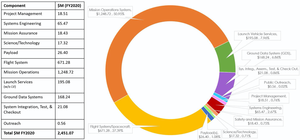
Figure 6.1.2 Total Project Cost Breakdown
6.2 Comparing Total Cost
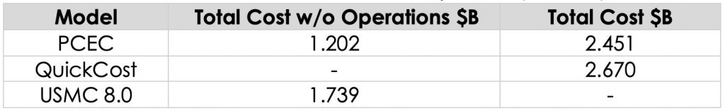
To put the customized PCEC model into perspective, the project cost was estimated using two alternate methods. These models have the same limitations as PCEC in terms of the nuclear power system and mission type. QuickCost from SMAD is a system level CER that was referenced to have an idea of how the projected cost of the mission would change as the proposal study continued. The model relies on a single CER that assumes various project and hardware components such as: dry mass and power, mission type and duration, team experience, and instrument properties. It assumes a high standard error rate of 41% as it is a broad stroke tool. One modification that needed to be made was the beginning of life (BOL) power. Like PCEC, QuickCost is not able to handle nuclear power sources, and so the EOL maximum expected power draw was entered. The USMC 8.0 model, Large Satellite Cost Model, and NASA Instrument Cost Model (NICM) were coupled together to have a preliminary estimation for all project cost excluding operations. Table 6.2.1 compiles the respective costs from the three models based on their capabilities.
Table 6.2.1 Cost Estimation Comparison (FY2020)
7.0 References
| [1] | NASA, “planetary,” [Online]. Available: https://www.planetary.org/blogs/casey-dreier/images/nasa-flight-mission-project-life-cycle.html. |
| [2] | N. Arrora, N. Strange and L. Alkalai, “Trajectories for a Near Term Mission to the Interstellar Medium,” JPL Technical Report Server, Pasadena, 2015. |
| [3] | P. Blanco and M. Carl, “Rocket Propulsion, Classical Relativity, and the Oberth Effect,” The Physics Teacher, vol. 57, no. 7, p. 439, 2019. |
| [4] | D. Landau and T. Lam, “Broad Search and Optimization of Solar Electric Propulsion Trajectories to Uranus and Neptune,” Advances in Astronautical Sciences, vol. 135, pp. 2093-2112, 2010. |
| [5] | N. Strange, D. Landau, R. Hofer, S. Snyder, T. Randolph, S. Campagnolar, J. Szabo and B. Pote, “Solar Electric Propulsion Gravity-Assist Tours For Jupiter Missions,” AIAA/AAS Astrodynamics Specialist Conference, pp. 1-9, 2012. |
| [6] | T. A. Pavlak, R. B. Frauenholz, J. J. Bordi, J. A. Kangas and C. E. Helfrich, “Maneuver Design for the Juno Mission: Inner Cruise,” American Institute of Aeronautics and Astronautics, 2014. |
| [7] | J. A. Sims and J. M. Longuski, “Analysis of V∞ Leveraging for Interplanetary Missions,” American Institute of Aeronautics and Astronautics, West Lafayette, 1994. |
| [8] | L. Weiss, “Cassini Controversy,” Mother Jones, 30 September 1997. [Online]. Available: https://www.motherjones.com/politics/1997/09/cassini-controversy/. [Accessed 20 April 2020]. |
| [9] | Technische Universitat Braunschweig, “MASTER (Meteoroid And Space debris Terrestrial Environment Reference),” Technische Universitat Braunschweig, [Online]. Available: http://www.space-systems.eu/index.php/de/master. [Accessed 27 March 2020]. |
| [10] | NASA JPL, “Voyager Did You Know,” [Online]. Available: https://voyager.jpl.nasa.gov/mission/did-you-know/. [Accessed 07 April 2020]. |
| [11] | NASA, “Space Launch System (SLS) Mission Planner’s Guide (MPG) ESD 30000, Rev. A,” NASA , 2018. |
| [12] | SpaceX, “Falcon User’s Guide,” January 2019. [Online]. Available: https://www.spacex.com/sites/spacex/files/falcon_users_guide_10_2019.pdf. |
| [13] | United Launch Alliance, “Delta IV Launch Services User’s Guide,” June 2013. [Online]. Available: https://www.ulalaunch.com/docs/default-source/rockets/delta-iv-user%27s-guide.pdf. |
| [14] | United Launch Alliance, “Atlas V Launch Services User’s Guide,” March 2010. [Online]. Available: https://www.ulalaunch.com/docs/default-source/rockets/atlasvusersguide2010.pdf. |
| [15] | M. Gibson, D. Poston, P. McClure, T. Godfroy, M. Briggs and J. Sanzi, “The Kilopower Reactor Using Stirling TechnologY (KRUSTY) Nuclear Ground Test Results and Lessons Learned,” NASA Technical Report Server, 2017. |
| [16] | M. Wall, “Nuclear Reactor for Mars Outpost Could Be Ready to Fly by 2022,” Space.com, 12 August 2019. [Online]. Available: https://www.space.com/nuclear-reactor-for-mars-outpost-2022.html. [Accessed 21 January 2020]. |
| [17] | J. E. Werner, S. G. Johnson, C. C. Dwight and K. L. Lively, “Cost Comparison in 2015 Dollars for Radioisotope Power Systems—Cassini and Mars Science Laboratory,” Idaho National Laboratory, Idaho Falls, 2016. |