Contents
- Electrical System
- Fuel and Carburetor System
- Internal Combustion
- Oil System
- Hydraulics and Gear
- The Pitot Static System
- The Gyroscopic System
Electrical System
The DC current electrical system of the Cessna 172 consists of three major components. There is the power generation, power storage, and users.
Power generation is done by the alternator system. A belt connected to a gear attached to the crankshaft rotates in the clockwise direction creating a magnetic field through the alternator outer coil of wire. This magnetic field creates electricity which is then sent to the battery. The alternator produces 60 amps of electricity and draws electrical power before engine start, when engaged by the left red rocker switch.
Power storage is done by the battery. The aircraft has a 28 volt battery located either behind the main instrument panel or mounted in the rear section of the aircraft. It is constantly being charged by the alternator, but when there is an alternator failure, the aircraft has about 30 minutes of battery power available to use.
Source: http://www.cfinotebook.net/notebook/operation-of-aircraft-systems/electrical
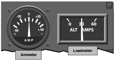
On the ammeter a discharge should be observed (needle to the left of the 0 amps) Load shedding, when a pilot turns of non-critical electrical instruments or radios, is needed in order to preserve the life of the battery. Individual circuit breakers will have numbers on them which denote the amount of amps it can take before popping.
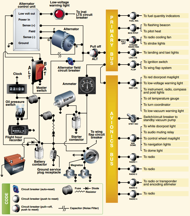
Electrical buses carry electricity to various systems on the plane. There are two buses; the primary bus and the avionics bus. The primary bus delivers power to the aircraft’s flaps, turn coordinator, lights, starter, and the pitot heat. The avionics bus delivers power to the radio stack which includes: Com 1 and 2, Nav 1 and 2, the audio switcher, the transponder, and any GPS or DME system installed.
Fuses and circuit breakers are important to the aircraft as they allow a circuit to “break” when an electrical system draws too much power. The breaker disconnects the instrument from the circuit to prevent damage to it as well as the rest of the systems. Fuses need to be pulled out and the filament tube must be replaced after the affected instrument is serviced. Circuit breakers can be pushed back in to reconnect the malfunctioning instrument to the electrical circuit. Remember that circuit breakers pop for a reason. Reset them only 1 time to prevent additional damage to other electrical systems.
A ground service receptacle, usually found in close proximity to the battery, sends a 5 amp fuse with power from an external source to power the start circuit. After engine start, the power is pulled and the alternator begins to charge the battery.
Quick Stats: 60 amps Alternator | 28 volts Battery | 30 minutes (roughly) before battery dies | Reset breakers only 1 time.
Source: http://www.cfinotebook.net/notebook/operation-of-aircraft-systems/electrical
Fuel and Carburetor System
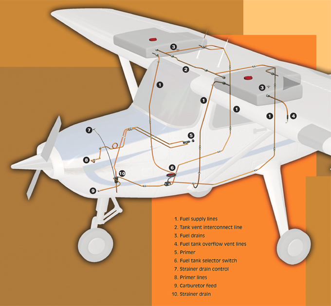
The major parts of the fuel system consist of the wing tanks, the selector valve, the primer, the carburetor, and the fuel strainer.

Source: http://www.atlantapilot.com/aircraft/172/Cessna%20Fuel%20System.jpg
Fuel is stored in two 21.5 gallon tanks located in the left and right wings with a crossfeed line between the two. 43 gallons can be filled, but only 40 are usable for flight. There is no fuel pump in the C172N/P, and so fuel is fed to the engine with the help of gravity.
As fuel is being consumed by the engine, a vacuum is created above the fuel within the tank. The pressure drop can be remedied by a crossfeed pipe, a small hole in the fuel caps, and a fuel vent protruding from the left wing tank. The crossfeed line enables the ambient pressure to reach the right wing tank as it doesn’t have a vent. Sometimes the vent can leak fuel if the aircraft is parked at an angle.
Fuel supply lines run from the tanks and flow to the selector valve located between the pilot and passenger. There is a fuel selector valve that has an: OFF, LEFT, BOTH, or RIGHT option. This handle regulates the flow of fuel to the engine and should be set to both when doing steep turns and during landing. After passing the selector valve, fuel is pumped to the carburetor or the primer system in order to reach the engine.
The primer system “squirts” fuel into the left 2 cylinders for engine start. Fuel is routed from the strainer drain to the cylinders direct. Once the engine has started, do not use the primer as it can cause engine damage.
Source: http://airplanegroundschools.com/Aircraft-Systems/Induction-Systems/index.html
The fuel strainer is the lowest point of the fuel system and is where fuel is sent to the carburetor or the primer. Gunk and residue builds up here as it is heavier than fuel and so a strainer drain is pulled during the preflight to remove some of the fuel.
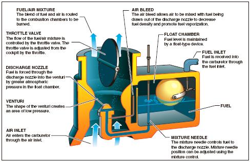
Fuel is then routed from the strainer drain to the the carburetor. The float type carburetor receives fuel from the fuel inlet. The inlet cap is regulated by a float ball system that opens the inlet as the fuel in the float chamber decreases. The fuel is then fed through the bottom via a small tube to the jet to meet with the incoming air. The mixture control, red knob in cockpit, controls the amount of fuel that is fed through the bottom tube. The mixture needle, which is linked to the mixture, sticks in or comes out of the bottom tube in order to regulate the fuel flow to the jet. Once past the jet, the fuel is mixed with the air for combustion.
Air flows into the carburetor through the intake filter in the front of the aircraft. Another source of air comes from around the manifold which is heated (used for carb. heat). In the event that the filter gets clogged or has icing, the alternate source can be used to supply air to the engine.
When the pressure is low enough, the temperature as a result can cause ice to develop in the carburetor. This occurs at or near the venturi, the throat of the carburetor where the fuel and air flow. Icing can form in temperatures up to 75 degrees fahrenheit with relatively high humidity conditions. In order to remove carb icing, air that flows path the manifold is used (engaging carb heat) to allow warm air to melt off the ice.
Internal Combustion
A butterfly valve at the top end of the carburetor regulates the amount of fuel/air mixture that enters the cylinders. This is the throttle control (black knob). During the intake cycle in the internal combustion engine, the cylinder is moving down creating a low pressure zone above it. The fuel/air valve is opened and this low pressure continues to form throughout the line (from the cylinder all the way to the carburetor). High pressure ambient air is fed from the filter and it pushes the fuel/air up the line and into the cylinder chamber for combustion. The cylinder comes back up and compresses the fuel/air mixture.
Source: https://en.wikipedia.org/wiki/Cylinder_(engine)#/media/File:4StrokeEngine_Ortho_3D_Small.gif
#/media/File:4StrokeEngine_Ortho_3D_Small.gif)
The magneto, two of them for redundancy and performance, creates a spark which is sent through the spark plug to ignite the fuel/air mixture and cause the cylinder to go down. After, the counter weight pushes the cylinder back up and the burned fuel/air exists the the combustion chamber.
INTAKE, COMPRESSION, COMBUSTION, and EXHAUST
Or… “suck, squeeze, bang, blow”
Oil System
The purpose of oil is to: clean the engine, lubricate bearings and other parts, and cool the engine.
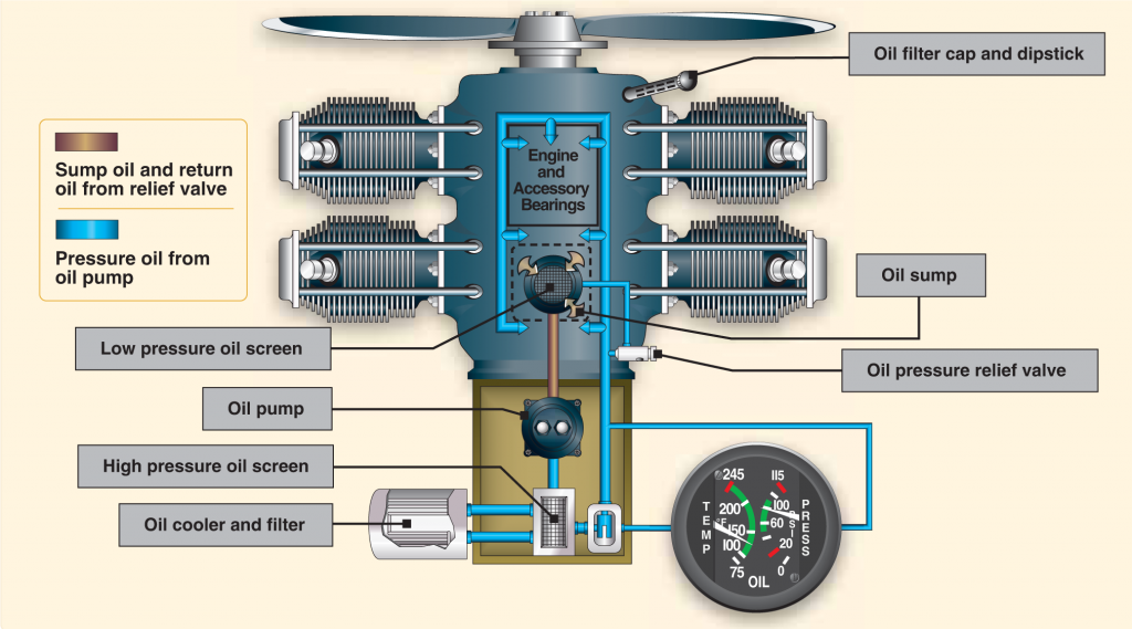
The main parts of the oil system are the sump, the engine driven pump, the filtration system, and the oil pressure and temperature gauges. Oil is fed into the aircraft through the strainer (has the dipstick with the yellow cap), usually 6 quarts for the 172 but can hold up to 7 quarts, and is sent to the sump. The sump is a reservoir. Oil is then pumped from the sump, through the engine driven pump, to the high pressure filter. The filter is mounted in the engine block and is difficult to service. Its objective is to remove any large particles or gunk that is in the oil. From there it goes through a second, easily serviceable filter, to be cleaned. After the oil has passed the filters it continues to the engine where it uses gravity to flow. On its way down it collects gunk, residue, provides lubrication, and cools the engine. At the bottom, it is collected and recycled back to the sump for the process to repeat. Oil starts out as a yellowish green color and ends up black as it cycles through the engine cleaning it.
Source: http://learntoflyblog.com/2015/11/09/aircraft-systems-oil-systems/
During the first 25 hours of a new engine, mineral oil is used in order to clean out the valves. Mineral oil has small particles which make it a bit more course than regular oil. These particles allow the oil to scrape off any excess metal trimmings or edges within the engine. The POH recommends MIL-L-6082 Aviation Grade Straight Mineral Oil. After the 25 hours, MIL-L-22851 Ashless Dispersant Oil, is required. Oil should be at or below 245 degrees fahrenheit with a pressure of 60-90 psi.
Hydraulics and Gear
The Cessna 172 has a tricycle landing gear system.
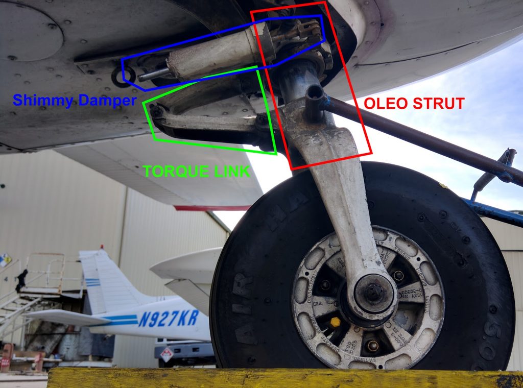
The nose gear is an oleo strut (piston) with a maximum turn angle of 30 degrees left or right (60 degrees total). It has attached to it a shimmy damper and a toque link (the triangle). The nose gear is steerable. The shimmy damper helps to reduce shimmy during takeoff or landing, and the torque link keeps the piston in line with the strut.
The main gear has a hydraulic line that is pressurized when the pilot applies the brakes. The hydraulic line is located behind the spring strut. The reservoir, located near the brake pedal, sends pinkish red hydraulic fluid through the line, down the strut, to the brakes for operation. They are hydraulically actuated disk-type brakes. The main landing gear shock absorption is done by a tubular spring-steel strut. Differential braking is used for tight turns.
The Pitot Static System
The pitot static system consists of a pitot tube, static port, alternate static port, airspeed indicator, altimeter, and vertical speed indicator. These instruments do not rely on electrical power to function.
VERY HELPFUL YOUTUBE VIDEO:
“Pitot-Static Instruments” by ERAUSpecialVFR
https://www.youtube.com/watch?v=kdFGbUouE_4
The Gyroscopic System
The gyroscopic static system consists of a engine driven vacuum pump, the attitude indicator, the electric turn coordinator.
Vacuum Pump
The dry vacuum pump supplies air due to a pressure difference. This airflow is used to spin the attitude indicator and heading indicator gyros. The pressure difference in the vacuum pump, compared to the ambient air, is around 5 inches mercury.
The vacuum pump has a plastic coupling that will shear in the event that the rotational torque is too slow, due to drag. This is in place to prevent the vac. pump from damaging the engine accessory gear which it is connected to.
More info. on Vacuum Pump:
https://www.avweb.com/news/maint/182905-1.html
Remember that in the event the vacuum pump fails, the gyros inside the attitude and heading indicators are still spinning. It will take a minute or two for them to fail completely. The attitude indicator and heading indicator will gradually become inaccurate during this time.
VERY HELPFUL YOUTUBE VIDEO:
“Gyroscopic Instruments” by ERAUSpecialVFR